Instructions for reading and writing iButton key (1-wire) using Arduino
We will need:
- Arduino (or compatible board);
- personal computer with Arduino IDE or other development environment;
- a key for an iButton or 1-wire intercom, a copy of which must be made;
- blank key for creating a “clone” of the original key (buy here);
- 1 resistor with a resistance of 2.2 kOhm (here is an excellent set of resistors of the most popular values);
- breadboard;
- connecting wires (like this).
Purpose of the intercom key duplicator
Using the Arduino microcontroller, you can copy the intercom key if you accidentally lost it.
RFID – radio frequency identification.
The device performs the same function as the barcode or magnetic stripe on the back of a credit card. It provides a unique identifier for this object. And just like a barcode or magnetic stripe, RFID must be scanned to obtain information. RFID is used in this project to read data from RFID tags and send the information to the non-volatile memory of the MCU.
The ID read from the tags is compared with the stored information, and if it matches, the door opens.
3Write Dallas Key ID using Arduino
Now let's write a sketch to write data into the memory of the iButton key.
Sketch of recording an iButton key using Arduino (expandable) #include // connect the library const int pin = 10; // declare the OneWire pin number iButton(pin); // declare the OneWire object on the 10th pin // key number that we want to write to the iButton: byte key_to_write[] = { 0x01, 0xF6, 0x75, 0xD7, 0x0F, 0x00, 0x00, 0x9A }; void setup(void) {
Serial.begin(9600);
pinMode(pin, OUTPUT); } void loop(void) {
delay(1000);
// delay for 1 second iButton.reset(); // device reset 1-wire delay(50); iButton.write(0x33); // send the “read” command byte data[8]; // array for storing key data iButton.read_bytes(data, 8); // read the attached key data, 8x8=64 bits if ( OneWire::crc8(data, 7) != data[7] ) { // check the checksum of the attached key Serial.println("CRC error!"); // if the CRC is incorrect, report it return; // and interrupt the program } if (data[0] & data[1] & data[2] & data[3] & data[4] & data[5] & data[6] & data[7] == 0xFF ) { return; // if the key is not attached to the reader, interrupt the program and wait until it is attached } Serial.print("Start programming..."); // start the process of writing data to the key for (int i = 0; i } // Initialize writing data to the tablet key iButton: void send_programming_impulse() {
digitalWrite(pin, HIGH); delay(60); digitalWrite(pin, LOW ); delay(5); digitalWrite(pin, HIGH); delay(50);
}
Don’t forget to set the number of your original key in the key_to_write array, which we learned earlier.
Let's upload this sketch to Arduino. Open the serial port monitor (Ctrl+Shift+M). Let's connect a key to the circuit, which will be a clone of the original key. The serial port monitor will display a corresponding message about the result of programming.
If this sketch did not work, try replacing the code after Serial.print("Start programming...") and before the end of the loop() function with the following:
Additional sketch of writing an iButton key using Arduino (expandable) delay (200); iButton.skip(); iButton.reset(); iButton.write(0x33); // reading the current key number Serial.print("ID before write:"); for (byte i=0; i<8; i++){ Serial.print(' '); Serial.print(iButton.read(), HEX); } Serial.print("\n"); iButton.skip(); iButton.reset(); iButton.write(0xD1); // write enable command digitalWrite(pin, LOW); pinMode(pin, OUTPUT); delayMicroseconds(60); pinMode(pin, INPUT); digitalWrite(pin, HIGH); delay(10); // print the key we are going to write: Serial.print("Writing iButton ID: "); for (byte i=0; i<8; i++) { Serial.print(key_to_write , HEX); Serial.print(" "); } Serial.print("\n"); iButton.skip(); iButton.reset(); iButton.write(0xD5); // write command for (byte i=0; i<8; i++) { writeByte(key_to_write );
Serial.print("*"); } Serial.print("\n"); iButton.reset(); iButton.write(0xD1); // command to exit write mode digitalWrite(pin, LOW); pinMode(pin, OUTPUT); delayMicroseconds(10); pinMode(pin, INPUT); digitalWrite(pin, HIGH); delay(10); Serial.println("Success!"); delay(10000); Here the writeByte() function will be:
int writeByte(byte data) { int data_bit;
for(data_bit=0; data_bit<8; data_bit++) { if (data & 1) { digitalWrite(pin, LOW); pinMode(pin, OUTPUT); delayMicroseconds(60); pinMode(pin, INPUT); digitalWrite(pin, HIGH); delay(10); } else { digitalWrite(pin, LOW); pinMode(pin, OUTPUT); pinMode(pin, INPUT); digitalWrite(pin, HIGH); delay(10); } data = data >> 1; } return 0; } It makes no sense to show a time diagram of the operation of the key identifier recording sketch, because It's long and won't fit in the picture. However, I attach the *.logicdata file for the logic analyzer program at the end of the article.
Intercom keys come in different types. This code is not suitable for all keys, but only for RW1990 or RW1990.2. Programming keys of other types may lead to key failure!
If desired, you can rewrite the program for a different type of key. To do this, use the technical description of your key type (datasheet) and change the sketch in accordance with the description. download the datasheet for iButton keys in the appendix to the article.
By the way, some modern intercoms read not only the key identifier, but also other information recorded on the original key. Therefore, it will not be possible to make a clone by copying only the number. You need to completely copy the key data.
The principle of operation of a duplicator on Arduino
Each key has an internal connection with the intercom door - this number serves as a key identifier. This intercom key number decides whether you have supplied the correct key. Therefore, the principle of operation of the intercom key duplicator on Arduino is quite simple: first you need to check the “allowed” key, and then assign the same number to another key clone.
By checking the number from its database of allowed data rates, it will open the door. The intercom keys that we will connect to the Arduino duplicator (sometimes called an iButton or Touch Memory) are read and written to the 1-wire interface. Therefore, the connection diagram is very simple.
Housing and Mechanical Assembly
I made a 3D model of a custom case for my duplicator.
STL file for printing a 3D model of the body and cover
Printed case
3D model of the body and cover .STL
Here's how it was printed on a 3D printer. I don't have a printer, but I found someone through the friendly printing service.
In order for the encoder board to fit into the housing, it needs to be slightly filed with a file from the end on which there are no tracks.
You can take a ready-made coil, for example from an rdm module, or buy it from the Chinese on Ali for 340 µH. If you wind it on a matchbox, that’s 59 turns.
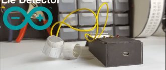
This is what the assembled device looks like.
Making a duplicator with your own hands
The LCD has 16 pins, which is too many for the Arduino Nano intercom, so it is important to have an I2C adapter. This allows the display to be controlled from just two signal pins on the Arduino. This is useful due to the small number of pins that will need to be controlled from the MCU.
LCD contacts
LCD displays have a parallel interface, which means that the MCU must control multiple interface pins simultaneously to control the display. The table below provides a description of each contact in English:
Contact specification
First, let's make connections between the LCD and I2C. This requires an I2C LCD display adapter (LCD1602). The adapter converts a 16 x 2 LCD into a serial I2C LCD that can be controlled via Arduino with just 2 wires.
Connections between Arduino and LCD
Necessary materials
- Arduino nano
- OLED display
- Encoder
- buzzer squeaker
- RGB LED
- Micro switch
- Battery contact
- Finished coil for 340 µH (10 pcs) and from RDM (1 pc)
- 3D model of the STL case
- Gerber PCB file
- Capacitor 4.7 nF - 1 pc.
- Capacitor 2.2 nF - 2 pcs
- Capacitor 10 nF - 1 pc.
- Resistor 0.25 W, 220 Ohm - 3 pcs.
- Resistor 0.25 W, 2.4 kOhm - 1 pc.
- Resistor 0.25 W, 10 kOhm - 1 pc.
- Resistor 0.25 W, 120 kOhm - 1 pc.
- Resistor 0.25 W, 510 kOhm - 1 pc.
- Diode 1N4148 - 1 pc.
- T5557 rfid key blank
- Dallas key blank RW1990
- Universal blank for metacom, digital and dallas TM-01a
Any capacitors are non-polar. I used 50V ceramic ones.
Hardware
To type the code you will need the LiquidCrystal_I2C.h library in the Arduino IDE. The library allows you to connect an LCD display to Arduino. The built-in LiquidCrystal_I2C library makes it easy to display characters on the LCD.
You can download LiquidCrystal_I2C.h from our website here, or from Github - https://github.com/todeilatiberia/SmartDoor.
Follow the instructions below to install the new library in your Arduino development environment.
- First download files from Github
. - Extract each folder from the archives.
- Copy the ZIP files to the Arduino folder.
- Open Arduino and add Keypad.zip: Sketch Menu -> Enable Library -> Add ZIP Library
- Add Keyboard Library: Sketch -> Enable Library -> Keyboard
2Reading iButton Key ID Using Arduino
There are ready-made libraries for Arduino to work with the 1-wire interface. You can use, for example, this one. Download the archive and unpack it into the /libraries/ located in the Arduino IDE directory. Now we can work with this protocol very simply.
Let's load this sketch into Arduino in the standard way:
Sketch of reading an iButton key using Arduino (expands) #include OneWire iButton(10); // create a 1-wire object on pin 10 void setup (void) {
Serial.begin(9600);
} void loop(void) {
delay(1000); // delay 1 second byte addr[8]; // array for storing key data if ( !iButton.search(addr) ) { // if the key is not attached Serial.println("No key connected..."); // report this return; // and interrupt the program } Serial.print("Key : "); for(int i=0; i}
This sketch shows the key number for the intercom, which is connected to the circuit. This is what we need now: we need to find out the number of the key we want to make a copy of. Let's connect the Arduino to the computer. Let's launch the serial port monitor: Tools Serial port monitor (or the keyboard shortcut Ctrl+Shift+M).
Now let's connect the key to the circuit. The port monitor will show the key number. Let's remember this number.
We remember the iButton key number displayed in the serial port monitor
And here is the exchange that takes place on a single-wire line when reading the key identifier (more details below):
Diagram of interaction between the Dallas key and Arduino via a single-wire interface (1-wire)
The figure, of course, does not show all the implementation details. Therefore, at the end of the article I attach a timing diagram in *.logicdata format, taken using a logic analyzer and the Saleae Logic Analyzer program and opened by it. The program is free and can be downloaded from the official Saleae website. To open the *.logicdata file, you need to run the program, press Ctrl+O or in the Options menu (located at the top right) select Open capture / setup.
Software part
We will connect a keyboard to display the numbers on the LCD for Arduino and copy the key we enter from the keyboard.
Keypad.h is a library that allows the Arduino to read a matrix type keyboard.
This project uses a 4×4 keyboard.
The table shows the connection between the Arduino board and the keyboard. The keyboard pins are connected to the digital output pins of the Arduino. Pin D6 was used for the buzzer because it was a PWM pin.
| Keyboard output | Arduino pin |
| 1 | D2 |
| 2 | D3 |
| 3 | D4 |
| 4 | D5 |
| 5 | A0 |
| 6 | D7 |
| 7 | D8 |
Connection between Arduino, LCD and keyboard
LCD and keyboard connected to Arduino
Then let's add RFID. In this case, the RFID board uses the SPI communication protocol, where the Arduino will act as the master and the RFID reader as the slave. The card reader and tags are designed to communicate at a frequency of 13.56 MHz.
This is an important step as it helps us read the data from the card and it will decide if the ID matches the information stored in the EEPROM. If it matches, it will give us access and display "Unlocked". Otherwise, the LCD will display “Locked”.
Connection between Arduino, LCD and RFID
Intercom on Arduino, LCD and RFID
The next step is to add a buzzer and 2 LEDs to simulate a controlled access system. Check out the chart below. The buzzer is set so that it buzzes whenever we gain access (unlocked). The red LED is always on when it is locked, but the green LED is on when it is unlocked.
To protect the modules, you need to use 3D printing of the housing. If you don't have a 3D printer, you can simply use a plastic housing that allows you to slot all the components inside. This is very useful because the modules will be placed inside and the only parts outside the box will be the LEDs, keyboard and LCD.
Wiring diagram showing the connection between Nano, LCD, Keypad, RFID and Beep
The code for downloading to the microprocessor is available at the link:
www.deviceplus.com/how-tos/arduino-guide/make-your-own-arduino-rfid-door-lock/
Making a universal RFID key for intercoms
Greetings to everyone who is interested in the topic of electronic keys-all-terrain vehicles. To be honest, I haven’t been following news in this area for a long time. But I want to publish my development from three years ago, since it is easy to repeat and may be of interest to someone. The bottom line: instead of a dozen keys with all-terrain codes and just codes, all the keys can be carried in one small device.
Disclaimer: I do not encourage repeating, assembly and use are your own responsibility, I am sharing information for informational purposes only. For example, to help companies servicing intercoms to patch “holes” in a timely manner if any are discovered using the device.
What it is? What can he do?
The device that I assembled back in 2022 is nothing more than a spoofer for an RFID intercom key operating at a frequency of 125 kHz.
The word “spoofer” in this case means that the device, although not essentially a key, pretends to be one, and intercoms react accordingly. The device can broadcast any key codes that are stored in its memory. Some codes can be found on the Internet by searching for “all-terrain keys”; I inserted them into the firmware first. But with some skill and desire, you can insert into the firmware the codes of all the RFID keys you use (if they operate at a frequency of 125 kHz), and thus be able to replace a bunch of key fobs with one device.
I know that there are a large number of diagrams of similar devices floating around the Internet. My goal was to create the simplest option available. Whether it was successful or not - judge for yourself.
What skills do you need to have to repeat this project?
First of all, skills in working with Arduino: have an installed development environment, be able to upload firmware to the board, install libraries, drivers, that’s all. Further. There is a place in the project where without soldering - well, no way. Therefore, you need straight hands and a soldering iron with consumables. Be able to read electrical circuit diagrams (or similar ones). Well, and programming skills in C++, in order to be able to customize the device. But this is already optional.
What spare parts are needed and how to install them?
Without further delay, here is a diagram of the device:
Sorry for the fact that it’s “not according to GOST” - I draw in Drawio, because the only free and convenient alternative to Visio, and now I only use licensed software. But I think everything is already very clear.
As you can see, the BOM for the basic version looks something like this:
- Arduino Nano (or any other Dunya that is at hand);
- RFID key of EM4100 format (instead of an inductor);
- npn transistor (any kind can be found, the frequencies here are not very high);
- 10K resistor;
- 560 pF capacitor (preferably SMD, you can solder directly into the case from the key);
- lithium-ion battery - to taste;
- three touch buttons;
- OLED display with I2C interface;
- charging module for liIon;
- boost DC-DC converter with 5 V output.
The power supply can be anything, as long as there is enough Arduino to start.
Input/output devices are similar: the firmware can easily be adapted to the buttons/displays that are available (the link to GitHub is just below). The current version of the firmware is written for an OLED display and touch buttons (taken for reasons of “bounce-free”). You can also assemble a test sample on a solderless breadboard. No special instructions are required here, except for how to deal with “inductance”. More about this.
A key similar to the one in the photo can be obtained from any local craftsman, or ordered from Ali. There is a cover on the key body that should be carefully opened once you get to the filling:
It consists of a coil and a memory chip with two contact pads on the sides. The coil leads are soldered exactly to these pads. All this is filled with a thin layer of elastic thermopolymer (similar in appearance and properties to hardened B7000 glue). To get the coil, I did the following. Taking a utility knife, I carefully pressed the PCB between the pads and the microcircuit with the blade. I separated the microcircuit from the coil and threw it away. Then, using a soldering iron, I carefully (so as not to unsolder the thin coil wires) burned the thermopolymer over the contact pads, making further continuity possible.
Before soldering, you should measure the resistance of the coil, making sure that it is not broken. If everything is in order, then it is better to assemble it this way: first solder the SMD capacitor to the contact pads (it should fit neatly between them), then the legs of the transistor and finally the resistor to the base. All this can be neatly mounted into the key body. Solder the ground and transistor base wires last.
Then make a hole in the key cover for these wires and close the key fob, giving it an almost original appearance. To assemble on a solderless breadboard, you should solder the pin connectors to the wires (or just tin them well so that you can easily insert them into the breadboard).
Firmware, test and adjustment
As promised, here is a link to the project repository.
The firmware files are located in the My_125_kHz_spoofer_v.03 folder. After assembly and uploading the firmware, the device is ready for use. To make sure it works, you don’t have to look for an intercom at all - you can get by with a Chinese module for reading RFID keys, called RDM6300, and another Arduino board (although for some it’s easier). I also put the firmware for the RDM6300 module, which produces the translated key code in the same format in which it is included in the spoofer firmware, into the project repository. The reader connection diagram is in the same place.
Procedure for testing using the RDM6300 reader:
- Make sure that the reader is working by bringing any of the available 125 kHz dongles to the antenna (data will be output to the COM port);
- Select the key code of interest in the spoofer menu;
- Bring the antenna close to the reader. If the reader read the same key as specified in the firmware, everything worked out! Else - we check the scheme, look for where the error is, eliminate it and start from point 1.
What can be changed in the firmware and what should not be touched?
Since the firmware was based on this code, which was not entirely clear to me, I moved the vital functions that cannot be changed at all into a separate tab functions.ino.
The rest of the program serves solely to provide the user with a comfortable opportunity to call the EmulateCard function (well, and a few lines of code before it). You can add your keys to the uint64_t universalID[] array located on line 75 of the code. Since I did not “define” the total number of keys in the device’s memory, and some functions are tied to this constant, when adding your own key, you should also change the limits within which the keyNumber variable, which is responsible for selecting the key, is located. Well, don’t forget to add your key to the menu. In general, everything is a little damp, but if you want, I repeat, it’s not difficult to figure it out.
What could be improved in the device?
- Add support for iButton keys (at least the most common ones from Dallas).
- Add emulation of keys operating at a frequency of 13.5 MHz (as I understand, either through wearing a rewritable blank and an RC522 module, or technically difficult, through real emulation).
- Add iButton, RDM6300 and RC522 readers to the device to make the device even more versatile.
Whoever succeeds, write about the results. I myself am not going to return to the development of this toy in the near future)
History of creation
It was autumn 2022.
As a second-year master's student, I was languishing with unresolved questions of self-determination. Simply put, I was idle and looking for something to do. As a result, I decided to complete my old engineering projects at the expense of attending university. The weather outside was simply magnificent. And what could be better than sitting somewhere on the roof of a high-rise building on a cool autumn night, drinking tea from a thermos and contemplating the bustle of the night city under your feet?..
During the day, getting into the entrance of any high-rise building is not difficult at all - social engineering from the series “Hello, a survey about the quality of work of the management company for the name_of_the_newspaper
“works great, and in general, mostly residents don’t mind someone coming into the entrance with them. At night it's a different matter. And I loved to climb out onto the roofs either at sunset or at night... A problem arose, which I solved using the method described above.
As I remember, information about such devices was not immediately found. Googling the keywords “intercom burglar” yielded almost nothing. The answer began to be found when I understood a little about RFID technology, and began to ask more meaningful questions, such as “RFID emulator”, “RFID multikey”, “RFID spoofer”.
As a result, I managed to find two decent English-language articles on the topic. In one, the author described how a key, rather complicated from a hardware point of view, was made on the basis of Arduino, and in the second, everything was the same, but without the source code, but with a very simple hardware part. Fairly judging that since both circuits are connected to the antenna with one Arduino pin, I decided to combine a simple hardware solution and open source. It was a success, albeit not the first time).
The photo at the beginning of this article is not the first version of the device. The first one was on a breadboard, and worked through a COM port. I remember how passers-by made it clear to me in every possible way that I looked suspicious
, when I stood at the door of a multi-storey building with an open laptop, and squealed something on the intercom.
Then there were several more compact versions that I assembled and disassembled for fun. The penultimate one was stolen by one of the main characters of my previous article. The current version was compiled on January 29 of this year, during a break between the lessons that I teach in my circle. It was assembled only to make sure that I do not misinform anyone, and the firmware and circuit work.
Testing and setting up a finished duplicator
For the project described above, you will need a special case to carefully place all the components and store them without damage.
You can design the enclosure using SketchUp, which has a user-friendly interface with simple buttons such as Eraser, Lines and Tape Measure Tool.
The box dimensions are: 120 x 125 x 37 mm .
If you are new to Sketchup, you should check out the following SketchUp tutorials:
https://www.sketchup.com/learn/videos/58
Box for the device body (top view)
Box for the device body (bottom view)
Before designing an enclosure for a project, the following aspects must be considered:
- Top view : - 2 holes for LEDs (5.2 mm). - 1 for LCD display (42.2 × 7.3 mm). — 1 hole for cable (16 × 10.5 mm).
- Bottom view : - 1 opening for keyboard (27 × 10 mm).
After this, you can compare the dimensions and build a plastic case. Moreover, you can change the design at your discretion.
Complete housing with modules located inside
4Description of the 1-Wire single-wire interface
Let's take a closer look at the One-wire interface. In organization, it is similar to the I2C interface: it must also contain a master device that initiates the exchange, as well as one or more slave devices. All devices are connected to one common bus. iButton devices are always slaves. The master most often is a microcontroller or PC. The data transfer rate is 16.3 kbit/sec. The bus in the idle state is at logic “1” (HIGH). This protocol provides only 5 types of signals:
- reset pulse (master)
- presence impulse (slave)
- writing bit “0” (master)
- writing bit “1” (master)
- read bit (master)
With the exception of the presence pulse, everything else is generated by the master. The exchange always occurs according to the following scheme: 1) Initialization 2) Commands for working with ROM 3) Commands for working with PROM 4) Data transfer.
1) Initialization
Initialization consists in the fact that the master sets the RESET reset condition (for a time of 480 μs or more lowers the line to “0”, and then releases it, and due to the pull-up resistor the line rises to the “1” state), and the slave no later than 60 µs after this must confirm presence, also lowering the line to “0” for 60...240 µs and then releasing it:
Initialization: 1-wire protocol reset and acknowledgment signal
2) Commands for working with ROM
If a confirmation signal does not arrive after the initialization pulse, the master repeats the bus poll. If the confirmation signal has arrived, the master understands that there is a device on the bus that is ready for exchange, and sends it one of four 8-bit commands to work with ROM:
| Name | Team | Purpose |
| Reading (Read ROM) | 0x33 | The master reads the first 64 bits of the iButton, which contain: 8 bits of the family code (*), 48 bits of the serial number and 8 bits of the checksum. |
| Match (Match ROM) | 0x55 | Access to a specific device with a known 64-bit number. |
| Search (Search ROM) | 0xF0 | Allows you to determine all 64-bit numbers of slave devices connected to the bus. |
| Skip ROM | 0xCC | Allows you to save time exchanging data with the key due to the fact that the master skips checking the serial number. It is not recommended for use in a situation where there are several slaves on the line. |
(*) By the way, there are quite a few families of iButton devices, some of them are listed in the table below.
iButton device family codes (expands)
| Family code | iButton devices | Description |
| 0x01 | DS1990A, DS1990R, DS2401, DS2411 | Unique serial number-key |
| 0x02 | DS1991 | Multi-key, 1152-bit secure EEPROM |
| 0x04 | DS1994, DS2404 | 4 kB NV RAM + clock, timer and alarm |
| 0x05 | DS2405 | Single addressable key |
| 0x06 | DS1993 | 4 kB NV RAM |
| 0x08 | DS1992 | 1 kB NV RAM |
| 0x09 | DS1982, DS2502 | 1 kB PROM |
| 0x0A | DS1995 | 16 kB NV RAM |
| 0x0B | DS1985, DS2505 | 16 kB EEPROM |
| 0x0C | DS1996 | 64 kB NV RAM |
| 0x0F | DS1986, DS2506 | 64 kB EEPROM |
| 0x10 | DS1920, DS1820, DS18S20, DS18B20 | temperature sensor |
| 0x12 | DS2406, DS2407 | 1 kB EEPROM + dual-channel addressable key |
| 0x14 | DS1971, DS2430A | 256 bits EEPROM and 64 bits PROM |
| 0x1A | DS1963L | 4 kB NV RAM + write cycle counter |
| 0x1C | DS28E04-100 | 4 kB EEPROM + dual-channel addressable key |
| 0x1D | DS2423 | 4 kB NV RAM + external counter |
| 0x1F | DS2409 | Two-channel addressable key with the ability to switch to the return bus |
| 0x20 | DS2450 | Four-channel ADC |
| 0x21 | DS1921G, DS1921H, DS1921Z | Thermochronous sensor with data acquisition function |
| 0x23 | DS1973, DS2433 | 4 kB EEPROM |
| 0x24 | DS1904, DS2415 | Real time clock |
| 0x26 | DS2438 | Temperature sensor, ADC |
| 0x27 | DS2417 | Real time clock with interruption |
| 0x29 | DS2408 | Bidirectional 8-bit I/O port |
| 0x2C | DS2890 | Single channel digital potentiometer |
| 0x2D | DS1972, DS2431 | 1 kB EEPROM |
| 0x30 | DS2760 | Temperature sensor, current sensor, ADC |
| 0x37 | DS1977 | 32 kB password protected EEPROM |
| 0x3A | DS2413 | Dual Link Addressable Switch |
| 0x41 | DS1922L, DS1922T, DS1923, DS2422 | High resolution thermochronic and hygrochronic sensors with data acquisition function |
| 0x42 | DS28EA00 | Digital thermometer with programmable resolution, serial mode, and programmable I/O ports |
| 0x43 | DS28EC20 | 20 kB EEPROM |
Data is transmitted sequentially, bit by bit. The transmission of each bit is initiated by the master device. When recording, the presenter lowers the line to zero and holds it. If the line holding time is 1...15 µs, then the “1” bit is written. If the holding time is 60 μs or higher, bit “0” is written.
Reading bits is also initiated by the master. At the beginning of reading each bit, the master sets the bus low. If the slave wants to send a "0", it holds the bus in the LOW state for a time from 60 to 120 μs, and if it wants to send a "1", then for about 15 μs. After this, the slave releases the line, and due to the pull-up resistor it returns to the HIGH state.
For example, this is what the timing diagram of the Search ROM (0xF0) search command looks like. The bit write commands are marked in red in the diagram. Pay attention to the order of the bits when transmitting over 1-Wire: the most significant bit is on the right, the least significant bit is on the left.
Timing diagram for sending the search command (0xF0) to the slave iButton
Further, if the previous command implies working with the PROM (reading and writing from the rewritable memory of the Dallas key), then the master sends a command to work with the PROM.
3) Commands for working with EEPROM
Before considering the commands for working with the iButton PROM, it is necessary to say a few words about the dongle memory structure. The memory is divided into 4 equal sections: three of them are intended to store three unique keys, and the fourth is for temporary data storage. This temporary buffer serves as a kind of draft where data is prepared for writing keys.
iButton key memory structure
There are 6 commands for working with EPROM:
| Name | Team | Purpose |
| Write to temporary buffer (Write Scratchpad) | 0x96 | Used to write data to a temporary buffer (scratchpad). |
| Read from temporary buffer (Read Scratchpad) | 0x69 | Used to read data from a temporary buffer. |
| Copy from temporary buffer (Copy Scratchpad) | 0x3C | Used to transfer data prepared in a temporary buffer to the selected key. |
| Write Password | 0x5A | Used to record the password and unique identifier of the selected key (one of three). |
| Write SubKey | 0x99 | Used to directly write data to the selected key (bypassing the temporary buffer). |
| Read key (Read SubKey) | 0x66 | Used to read the data of the selected key. |
4) Data transfer
To be continued…