History of the creation of the IL-76 aircraft
The Il-76 aircraft was created at the S.V. Ilyushin Experimental Design Bureau under the leadership of Deputy General Designer G.V. Novozhilov and is intended for transporting and landing personnel, equipment and cargo for various purposes.
Il-76 is the first military transport aircraft in the history of our country with turbojet engines, which is capable of delivering cargo with a maximum weight of 28-60 tons over a distance of 3600-4200 km with a cruising speed of 770-800 km/h.
Thanks to its unique engineering and technical qualities, the Il-76 has become the most common military transport aircraft in the world, the potential of which continues to develop today and is embodied in new modifications of military and civil aircraft.
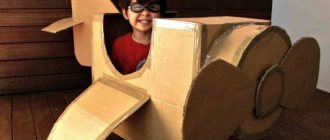
The aircraft model, despite its small size, retains all the beauty and power of the Il-76 military transport aircraft.
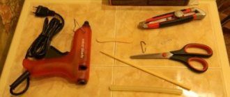
To make it you will need the following materials and tools:
- One sheet of foam ceiling tiles 3-4 mm thick, size 500x500 mm.
- Glue "Titan".
- Stationery knife.
- Ballpoint pen or felt-tip pen.
- Fine-grit sandpaper.
- Stationery needles.
- A sheet of plywood measuring 500x500 mm (for use when cutting, so as not to damage the table surface).
Materials
To build the models, square ceiling slabs made of extruded polystyrene foam are used (foam is the kind that bowls for Doshirak are made from, not to be confused with ball ones) with a size of 500x500 mm and a thickness of 3 and 4.5 mm, and there is also a size of 1000x150 mm.
To strengthen the edges and spars, threads drawn from a clothesline are used. Glue – NACET-R or “Titan”. Epoxy resin is too rigid and, when deformed, cuts the foam like a knife.
How much does all this cost? For example, eight ceiling panels cost 90 rubles in Moscow (enough for 3-5 models), a bottle of Titan glue 0.5 liters - 42 rubles (in three years of training with foam plastic models, I used up half the bottle), a roll of adhesive tape - 10 rubles ( enough for a dozen airplanes), and a coil of rope - 10 rubles (enough for more than one hundred models).
Model aircraft structure
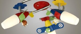
The design of all models is very similar. The main components of the radio-controlled airplane model are shown in the photo.
This:
Fuselage. This is the basis of the entire model on which the following are mounted:
- bearing structures;
- tail section;
- chassis.
Installed inside:
- engine;
- aircraft control equipment: receiver, steering controls, batteries.
- Wing.
Serves to create lifting force. The wing keeps the model in the air. - Ailerons
are control surfaces located at the rear end of the wing and deflect up or down in antiphase. They allow the plane to tilt left and right. - Tail unit
. It consists of a vertical part - the keel, and a horizontal part - the stabilizer. This device provides stability to the aircraft so that it can fly straight and level without tumbling in the sky, randomly changing the direction of its movement.
The rudder is installed at the rear end of the keel.
Chassis. Allow the model to take off from the surface and then land on it.
- Engine
. Creates the movement of the model, allows it to gain the desired height, and then maintain a given speed. - Buck
. Serves for the fuel needed to run the engine.
- Receiver
. Receives the transmitter signal, amplifies it, processes it and transmits it to the steering gears. - Steering cars
. The signal coming from the receiver is converted into moving the model's rudders through the connected rods. - The receiver and machine are powered by an on-board battery
. Usually these are four “finger” elements.
Model aircraft structure
The design of all models is very similar. The main components of the radio-controlled airplane model are shown in the photo.
This:
Fuselage. This is the basis of the entire model on which the following are mounted:
- bearing structures;
- tail section;
- chassis.
Installed inside:
- engine;
- aircraft control equipment: receiver, steering controls, batteries.
- Wing.
Serves to create lifting force. The wing keeps the model in the air. - Ailerons
are control surfaces located at the rear end of the wing and deflect up or down in antiphase. They allow the plane to tilt left and right. - Tail unit
. It consists of a vertical part - the keel, and a horizontal part - the stabilizer. This device provides stability to the aircraft so that it can fly straight and level without tumbling in the sky, randomly changing the direction of its movement.
The rudder is installed at the rear end of the keel.
Chassis. Allow the model to take off from the surface and then land on it.
- Engine
. Creates the movement of the model, allows it to gain the desired height, and then maintain a given speed. - Buck
. Serves for the fuel needed to run the engine.
- Receiver
. Receives the transmitter signal, amplifies it, and processes it. And then it transmits to the steering gears. - Steering cars
. The signal coming from the receiver is converted into moving the model's rudders through the connected rods. - The receiver and machine are powered by an on-board battery
. Usually these are four “finger” elements.
Where to start designing an aircraft model?
We start with the fuselage, or rather, first a drawing is made, and then the preparation of parts begins. We make blanks, cut off the edges, then glue two planes in the center using “Titanium”, after which lines are drawn and “pressed” on the blank along which the fuselage will be bent, which, in our case, will consist of three parts. The beauty of this is that if damaged, the part can be easily replaced.
We do the same with blanks for future wings, the span of which will be approximately 1.5 m (taking into account the size of the ceiling 50x50mm).
You also need to use a special corner, sold in construction stores (in the same place as the ceiling). Its size is 60X43. A screw will be attached to the wide part.
Motor installation parameters, scale selection, drawings
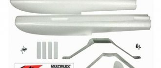
Initially, I did not intend to make new purchases, having the following inheritance from the first aircraft:
- motor Power 280
- controller RSC 110 BEC
- battery of 7 NiCd 370 mAh cans
- screw ARS 10x7
The wingspan of the future model was seen to be around 900 mm, which easily matched the original in 1:11 scale. I stumbled on the wing profile - all available drawings report that “exact airfoil unknown, engineers found section to be near identical to the NACA 2300 series,” and more specifically, from the root NACA 2315 to the NACA 2310 at the end. I found a useful resource on NACA profiles online: https://www.nasg.com/afdb/list-airfoil-e.phtml. It works for 30 days without registration - that’s enough.
With its help, a set of wings with a variable profile were drawn: from NACA 2312 (12% relative thickness) at the root rib to NACA 2309 at the tip. The angle of attack was taken from the original - 1.75 degrees. The desired dimensions and data of the engine mount were loaded into MotoCalc, which showed that such an aircraft would fly if it did not exceed the take-off weight of 400 grams.
Of the drawings I found online, the one below has the best quality.
Drawing Me-109e plan.zip 305.74 kB
Here's what we did (video)
- How to make crafts from ceiling tiles with your own hands: ideas, video
A winter's tale from polystyrene foam After each repair, a certain amount of waste of certain building materials remains. Don't rush them... - How to glue ceiling tiles onto tiles correctly An interesting solution This material is a fairly simple and “budget” ceiling covering. These are, most often, square panels for making...
- How to glue ceiling tiles: different gluing methods, location options (photos, videos) |
PROceilings Almost any repair work affects the ceiling surface. There is a large selection of ceiling finishes. This may be the whitewash familiar to many...
Airplane ceiling tiles
An aviation legend in miniature. Aeromodelling is a great activity that is suitable for both boys and grown men. A love of airplanes, as well as a little patience, is probably all that is needed to make a good model. A pleasant fact is that the materials that we need are completely insignificant in cost. You can buy them at any hardware store. The Su-34 aircraft is a legendary combat vehicle that has served the Russian army as a fighter-attack aircraft for several decades. In this master class, we will make a model of this aircraft that can be flown, or simply used as a souvenir. To make the model, we need: 1. Ceiling tiles.2. Polystyrene foam up to 20 mm thick.3. Glue "Dragon".4. Stationery knife.5. Sandpaper.6. Marker.7. Plasticine. To begin with, we will make parts from ceiling tiles. To do this we need to draw them and cut them out.
Popular articles Memorial ribbon for RadonitsaIt is important to note that the dimensions of the parts in this case are not important, however, proportions and symmetry should be maintained as in the photograph. Unlike the hull (1) and fins (2.2*), the air intakes (3.3*) need to be glued together from three parts, as in the photo, the gluing line is indicated in green
When the air intakes are ready, you can glue them to the body; the gluing line is indicated in orange.
Then glue the keels according to the red line.
When the glue under the fins is almost dry, you need to move them slightly (1 - 3 mm from a flat position) at the top, this will give the plane better stability in the air. This can be done simply by inserting a stick of the appropriate size between the keels for a few minutes. Next, we need to make the fuselage, which consists of rear and front parts, each of them divided into lower and upper. Let's draw the details, cut them out and sand them with sandpaper. Part number three must be made in duplicate. Now that all the components are ready, you can start gluing them together.
Colored lines should be used in the same way as the previous details. The fighter is ready.
It can be decorated in camouflage style, or any other, depending on your personal wishes. However, such a model cannot yet fly, because it has low weight and an uneven distribution of this weight throughout the body. In order for an airplane to glide, it must be balanced. This can be done experimentally by gluing pieces of plasticine of different sizes to the nose of the plane. The place where you need to load the model is shown in the photo.
If the fighter glides smoothly, the amount of cargo has been chosen correctly. A properly made model can fly about 25 meters. If there are problems with starting the plane, then literally 5 - 15 minutes of training, and everything will be fine. The plane will give you and your children an unforgettable experience. Successful flights to you! With respect, Vinogradny brothers.
Expanded polystyrene, foam plastic
Expanded polystyrene is a modern and affordable material that is easy to use. Expanded polystyrene is a white, lightweight product that is an environmentally friendly, heat and sound insulating material. It consists of 98% air and 2% polystyrene foam. The pentane fraction of hydrocarbons is used as a foaming agent, which is then converted into carbon dioxide and water. In the EU countries, independent tests were carried out by the German Federal Office for Environmental Affairs on the flammability of polystyrene foam with anti-perrhenic additives and mineral wool. Mineral wool and expanded polystyrene belong to the same class of combustible materials: class A in accordance with DIN 4102. The biological safety of expanded polystyrene is confirmed by the Institute for Bioengineering Research (Karsfeld, Germany)
Despite the apparent similarity of the properties of mines. cotton wool and expanded polystyrene, cotton wool is significantly inferior to expanded polystyrene in a number of properties.
Compared to expanded polystyrene, mineral wool has low strength and does not have load-bearing capacity and tends to sag after being wound onto a pipe.
Its other disadvantage is discomfort during installation and a tendency to absorb water, which reduces the insulation coefficient. Each percentage of moisture contained in mineral wool worsens the thermal conductivity coefficient (compared to the dry state) by an average of 6-8%.
For expanded polystyrene, for every 1% water content, the thermal insulation properties deteriorate by 3.8%, and after drying they are almost completely restored.
Heat-insulating materials based on organic polymers such as polystyrene foam, having a closed cell structure, have extremely low water absorption, negligible vapor permeability and are non-hygroscopic. For example, the water absorption of polystyrene foam when immersed in water for 7 days is only 0.5-1.5% of the volume. Therefore, such materials are well suited for insulating structures and engineering communications that are subject to abundant moisture: heating networks, water pipelines, etc.
Non-hydrophobic mineral wool grades are capable of absorbing significant amounts of moisture (up to 200-300% by volume). This significantly reduces the service life of materials and also creates an unfavorable chemical environment for protected load-bearing structures or utilities. That is, the durability of thermal insulation materials in building structures, in addition to the properties of the materials themselves, directly depends on the degree of moisture of the thermal insulation material
Model aircraft structure
The design of all models is very similar. The main components of the radio-controlled airplane model are shown in the photo.
Components of an aircraft model
This:
Fuselage. This is the basis of the entire model on which the following are mounted:
- bearing structures;
- tail section;
- chassis.
Installed inside:
- engine;
- aircraft control equipment: receiver, steering controls, batteries.
- Wing. Serves to create lifting force. The wing keeps the model in the air.
- Ailerons are control surfaces located at the rear end of the wing and deflect up or down in antiphase. They allow the plane to tilt left and right.
- Tail unit. It consists of a vertical part - the keel, and a horizontal part - the stabilizer. This device provides stability to the aircraft so that it can fly straight and level without tumbling in the sky, randomly changing the direction of its movement.
The rudder is installed at the rear end of the keel.
Chassis. Allow the model to take off from the surface and then land on it.
- Engine. Creates the movement of the model, allows it to gain the desired height, and then maintain a given speed.
- Tank. Serves for the fuel needed to run the engine.
Airplane controls
- Receiver. Receives the transmitter signal, amplifies it, processes it and transmits it to the steering gears.
- Steering machines. The signal coming from the receiver is converted into moving the model's rudders through the connected rods.
- The receiver and machine are powered from the on-board battery. Usually these are four “finger” elements.
Assembly of the structure
Once all the elements are ready, you can begin assembling the product. First of all, on the fuselage, mark the place where the stabilizer will be installed. The corresponding mark is on the drawing, so you can simply transfer it.
Next, use a knife to make a slot along the mark, which should correspond in size to the width of the stabilizer. A small amount of foam glue is applied to the stabilizer and it is installed in place, as shown in the photo above.
The next step to assemble the aircraft is to glue the parts with the cabin on both sides to the base. There should be two of them, and they are distinguished by the presence of a protruding element on top. The glue must be applied in a small layer over the entire plane of the elements to achieve good adhesion.
Parts without a cockpit are glued on top of the elements with an aircraft cabin. There should also be two of them and they differ from the previous ones only in the absence of a corresponding protrusion. This is done in order to increase the overall thickness of the aircraft for better aerodynamics.
Using a cardboard cutout, a mark for the location of the wing is transferred to the aircraft body. A through cut is made using a knife along the mark. Its size should not exceed the thickness of the sheet so that it can be well fixed inside.
The wing is initially not inserted all the way. This is done so that it can be smeared with glue on both sides; only after applying the glue can the wing be aligned the way it should be installed.
In order for the model to have better aerodynamics, it is necessary to get rid of sharp corners. A stationery knife and fine sandpaper will help with this. First of all, the corners are carefully cut with a knife. The layer should be minimal so as not to damage the structure. After this, you need to sand the product with fine sandpaper to give it a finished look.
The model will be launched using a special fixture. Therefore, it is necessary to make a small trigger for it. To do this, you will need a piece of skewer, which is fixed directly in front of the wings at an angle of 45 degrees.
The nose of the aircraft is additionally covered with glue. This will give it more rigidity, and the front part will not be deformed when dropped. In addition, this will create additional weight for balancing.
The launch catapult is assembled from a fishing elastic band, a small stick and electrical tape.
The elastic band must be folded into a loop, as shown in the photo, and secured to the stick with electrical tape. Before launching the model from the catapult, it is necessary to ensure that the aircraft glides. It is manually run several times to determine which part needs to add weight to make the model glide.
Popular articles Cool wishes for Maslenitsa in verse, SMS and proseTo start the model, you need to insert part of the skewer into the elastic band, tighten it and release it. You need to launch the plane parallel to the ground, this will give lift and it will take off. If you launch it upward, it will fall into the ground. To make the model easier to find after launch, you need to paint it in bright colors that will not blend in with its surroundings. The full assembly video is posted below.
Technology
Plates with a thickness of 3 mm are cut in half using 0.2 mm nichrome wire to a thickness of 1.5 mm, after which they are used as sheathing. I cut the spar and leading edge from 4.5 mm foam, and the ribs from 3 mm.
I cut foam plastic like this: I stretch a nichrome wire across a piece of fiberboard measuring 60x100 cm in the middle: on one side tightly, on the other through a spring, from the edges I place coins of the appropriate thickness under the wire, and then I connect the current source. I place the ceiling panel, another sheet of fiberboard measuring 50x50 cm on it and evenly guide this “sandwich” through the wire. It turns out two panels 1.5 mm thick - they are suitable for covering the wing.
Nichrome is heated by an regulated power supply with a voltage of up to 30 V. The voltage is selected so that the thread cuts the panel well and does not melt it too much when the movement of the foam stops during cutting.
Foam plastic tends to stretch, which is why a wing without threads will be flimsy in terms of twisting and deflection. The solution to the problem is threads glued along the spar (between the spar and the skin) and along the leading edge. They give the wing the necessary rigidity.
I take threads from clotheslines. The ropes are white, the material is some kind of synthetic, they are sold on every corner. They are a woven tube; the threads themselves are not twisted and do not stretch or spring at all - unlike simple threads.
If you take a ceiling slab and deform it, you will immediately notice that it bends much easier in one direction than in the transverse direction. This must be taken into account (and used!) when cutting out blanks for both the fuselage and the wing, stabilizer and fin. The panels can be bent on the edge of the table, like cardboard or paper.
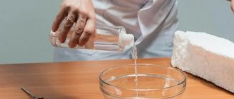
A little about glue. It should be thick - the same as it is sold. I tried diluting it with alcohol and denatured alcohol - unfortunately, it doesn’t hold well when it dries, so I don’t recommend diluting it.
Aircraft modeling
Model airplane construction is a popular technical sport that is of interest to schoolchildren, students, workers and engineers. At the same time, everyone chooses for themselves a class of aircraft models that suits their interests.
In aircraft modeling there are three fairly large groups of aircraft models, presented in the table:
| Model class | Peculiarities |
| In such models, designer intervention is impossible during flight. All adjustments and settings of the aircraft are completed when it is launched. They can be: - motorless - gliders; - with a simple, very small, internal combustion engine, which is attached to the body with an elastic band. The motors on the models work for a few seconds to throw the light-winged structures up to a hundred meters up, and then they smoothly go down. Timers or special clock mechanisms are used to turn off the engine and switch the steering wheel to planning. | |
With such models, the athlete controls wire threads, which are called cord. The devices fly in a circle with a diameter of approximately 40 meters. The “pilot” is located in its center with the control stick. When you pull the handle towards yourself, the elevator deflects, and the device obediently flies up. And moving the handle away from you causes the model to descend. The devices are:
| |
| Controlled remotely, wirelessly. For this purpose, there is a set of radio equipment, which includes a transmitter, in the hands of the operator, and a receiver with steering control mechanisms, mounted on board the model. |
Quick production of a semi-copy aircraft model from ceiling tiles
Quick production of a semi-copy aircraft model from ceiling tiles
Although recently a lot of aircraft models have appeared in model shops, nevertheless, many aircraft modelers prefer to make models themselves.
One of the most common materials used is ceiling tiles. This is a good material for aircraft modeling. Ceiling tiles are not subject to rotting, do not absorb moisture, and are easy to process and glue. Sheets without volumetric embossing are used.
Here is an example of the manufacturing technology for the volumetric fuselage of the P-51D aircraft model.
The main idea of this technology is that cut flat pieces are glued together, thus forming a three-dimensional structure. The technology is simple, does not require much skill and is accessible to the beginning aircraft modeller. All you need to do is download the aircraft model drawing, print it, transfer it to the ceiling tile, cut it out and glue it together.
Here is a 3D sketch of the future fuselage.
Fuselage layers cut from ceiling tiles.
This is what the glued fuselage will look like.
The 5 central parts of the fuselage are glued together. Titanium ceiling tile adhesive is used. Servos are installed in the center to control the rudder and elevator.
After installing the servos, pieces of the ceiling are glued in to secure the servos. You can use a heat gun for additional fixation.
The remaining layers of the fuselage are glued on.
The fuselage is ready, you can start processing it.
Using fine-grain sandpaper, we give the fuselage a streamlined shape, smoothing out the transitions between the layers of the ceiling tiles.
Carefully cut off the upper part of the fuselage to have access to the equipment.
The wing and tail are installed. The wing is also made of ceiling tiles.
The ailerons are cut into the wing and servos are installed. After installing the engine, the model looks like this.
To give it a replica look, the Mustang P-51D aircraft model is painted.
The aircraft model is painted with acrylic paints.
Electronics are installed inside the fuselage. Receiver, running battery, electric motor speed controller.
Aircraft model ready to fly.
The aircraft model turns out to be very resistant to impact damage. The glued layers of ceiling tiles give the fuselage greater strength. It is worth noting that factory models are made from ball foam or balsa. In both cases, they are tens of times inferior in strength to a homemade puff fuselage. If you do not take into account the time spent on external finishing - painting the fuselage, applying inscriptions, etc., then an aircraft model using this technology can be assembled in a couple of evenings.
Fuselage
It consists of two parts connected end-to-end along a frame in the area of the first third of the wing chord. This trouble is caused only by the size of the source material - the length of the panel is simply not enough for the entire length of the fuselage.
The frames are cut out of foam plastic and placed in the locations of the fuselage sections on the drawings
Please note - frames are located only in places of the 1st, 2nd, 3rd, 4th, 6th and 9th sections. Each part of the fuselage consists of two sidewalls, a bottom and a top
The sidewall patterns are marked on the drawing with an indentation (0.5-1.5 cm) inward from the contour line. The marking of all points of contact and center lines are transferred from the drawing to the frames and sidewalls before cutting. The bottom and top are cut in place with the sidewalls glued to the frames.
Each part of the fuselage consists of two sides, a bottom and a top. The sidewall patterns are marked on the drawing with an indentation (0.5-1.5 cm) inward from the contour line. The marking of all points of contact and center lines are transferred from the drawing to the frames and sidewalls before cutting. The bottom and top are cut in place with the sidewalls glued to the frames.
Sequence when gluing:
— frames to one side according to the markings until the glue dries; — the second sidewall to the frames according to the markings until the glue dries; - bottom to frames/sidewalls until the glue dries; - top until the glue dries.
The compartment from the end of the cockpit canopy to the third frame is made in the form of a removable cover for access to the on-board equipment. The cockpit canopy is made of transparent plastic from office folders. The ribs of the lantern are made of non-glossy tape and then painted. The pilot is foam plastic with coloring.
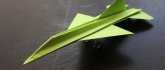
How to make an airplane from ceiling tiles
You can make a simple airplane from ceiling tiles in just a few hours. Materials for these purposes will require:
- Several foam ceiling tiles;
- A small piece of plywood to strengthen the nose of the glider;
- A piece of cardboard or paper from which to sketch and cut out a template.
In order to make a small glider with your own hands, you will need the following tools:
- Scissors;
- Ceiling tile adhesive;
- Pen and ruler;
- Hacksaw for cutting out the nose of the glider.
After all the materials and tools have been prepared, you can begin cutting out the template and assembling the airplane from the ceiling tiles.
Marking and cutting out the glider template
It is advisable to first sketch out the glider drawing on a piece of cardboard, after which you can begin cutting it out of the ceiling tiles. You should start with the fuselage, its length is 45 centimeters. At the same time, the width of the airframe fuselage, in different parts, from the nose to the tail, will be within 7-10 cm.
The length of the aircraft's wings made from ceiling tiles is 30 cm, with a width of 19 cm, and the length of the tail is 11 cm, with a width of 7 cm. The nose of the glider, as mentioned above, is reinforced with a small piece of thin plywood, which will significantly extend the life of the homemade model in the process of its launch.
According to the template, you will need two parts of the fuselage and wing, which will be glued together during assembly, and the tail.
What tools are needed?
Lumpy foam or foam ceiling tiles. The tile is more convenient in the sense that it is easier to cut, and its width will be the same throughout the entire part. The undoubted advantage of piece foam is the fact that you don’t need to buy it. Almost every person has it in their home and is great for children's crafts.
Stationery knife or scissors. If a child independently looks for the answer to the question of how to make a plane out of foam plastic, then it is better to give him scissors. If the creative process will be controlled by parents, then it is better to use a stationery knife.
Glue. You can take regular PVA, it is suitable for gluing foam. But if you want to assemble a model airplane quickly, then it is better to use Moment glue or its equivalent.
Paper or cardboard for patterns.
Additional details. Their number and name will depend on the type of aircraft you want to assemble. This may include paper clips, skewers and rubber bands - this is necessary for a model airplane with a rubber band motor. You may also need a radio-controlled motor (for example, from an old radio-controlled car). If you are wondering how to make an airplane out of foam and wood, then you will need sheets of plywood, which will later become wooden parts.
Cut out the airplane according to the template and glue it with your own hands
It is better to do modeling on a table designed for technical creativity. The foam should be cut on a flat surface; it is convenient to use a sheet of plastic or plywood. The sequence of actions is as follows:
- First of all, it is necessary to make drawings of the parts of the future aircraft model from foam plastic. Using the photo below, you can draw them on checkered paper. There are 4 types of parts in total, 3 of which need to be made in duplicate.
- When the drawings are ready, you can cut out the templates for the necessary parts.
- Next, we apply the templates to the foam tiles and trace them along the contour. As you can see, all the blanks, except for the main, largest one, need to be marked twice.
- The material is best cut with a stationery knife, and it is better to keep its blade almost parallel to the plane so that the edges are smooth. The result is details like these.
- No matter how perfect the cut is, in some places it is still necessary to correct our workpieces. Sandpaper will come in handy here, with which you need to process all the details.
- Now we take the tail parts, which have the shape of a rectangular trapezoid, and glue them to the back of the tail blank, parallel to each other. To secure them during the gluing process, you can use needles or pins. To dry quickly, place the workpiece on a radiator or in the sun.
- The remaining two types of parts also need to be glued together - long with long, short with short. For better fastening, it is better to compress them with clothespins. After this, they are also placed in a warm place to dry.
- While the parts are drying, you can make a slingshot to launch the airplane, which will serve as a motor. For this you will need a wooden stick and an elastic band. The stick should be round so that it is comfortable to hold, and its height should be about the size of a fist. You can use a regular elastic band, but it is quite elastic.
- You need to make a cut in the top of the piece of wood using a knife or saw. It does not need to be made too large, but the elastic should be inserted there with some effort. The depth of the incision is made no more than 1 centimeter.
- Now we put an elastic band into the resulting cut. If it pops out when pulled, you can secure it with glue.
- We take out the glued parts. Using the same sandpaper, they can be made absolutely even at the joints.
- Glue the finished parts to the base. At the top, where the tail guides are already glued, we place a shorter part; accordingly, there should be a longer part on the lower surface of the aircraft. They need to be glued strictly in the center of the model.
- We use an awl or a screwdriver to make a hole in the joint between the lower parts at the nose of the plane and glue a match there at an angle of approximately 45-60 degrees. The match head needs to be removed and may need to be shortened.
- Next, take a small piece of plasticine and glue it onto the nose of the plane to make it a little heavier in this place.
Popular articles Congratulations on April Fool's Day
Hood
Initially, when making the hood, I wanted to follow the example described in E. Rybkin’s article, but after several attempts I found this method a little complicated for me. As a result, I decided to make a hood from a strip of ceiling. I cut out a rectangle 70mm wide and about 300mm long, applied it to the nose of the plane and wrapped it. The bottom was glued with tape. An important point here is the correct choice of the direction of bending of the ceiling. In my case, there was no need for heating or other methods used to shape the ceiling. I wanted to use a propeller from a processor cooler as the front of the motor, but I haven’t found the right size yet. This would help solve the engine compartment ventilation problem. For now, I limited myself to sticking printed blinds from the drawing.
Aircraft modeling
Model airplane construction is a popular technical sport that is of interest to schoolchildren, students, workers and engineers. At the same time, everyone chooses for themselves a class of aircraft models that suits their interests.
In aircraft modeling there are three fairly large groups of aircraft models, presented in the table:
| Model class | Peculiarities |
| Free-flying vehicle | In such models, designer intervention is impossible during flight. All adjustments and settings of the aircraft are completed when it is launched. They can be: - motorless - gliders; - with a simple, very small, internal combustion engine, which is attached to the body with an elastic band. The motors on the models work for a few seconds to throw the light-winged structures up to a hundred meters up, and then they smoothly go down. Timers or special clock mechanisms are used to turn off the engine and switch the steering wheel to planning. |
| Line plane | With such models, the athlete controls wire threads, which are called cord. The devices fly in a circle with a diameter of approximately 40 meters. The “pilot” is located in its center with the control stick. When you pull the handle towards yourself, the elevator deflects, and the device obediently flies up, and deflecting the handle away from you causes the model to descend. The devices are:
|
| Radio controlled model | Controlled remotely, wirelessly. For this purpose, there is a set of radio equipment, which includes a transmitter, in the hands of the operator, and a receiver with steering control mechanisms, mounted on board the model. |
Aircraft modeling
Model airplane construction is a popular technical sport that is of interest to schoolchildren, students, workers and engineers. At the same time, everyone chooses for themselves a class of aircraft models that suits their interests.
In aircraft modeling there are three fairly large groups of aircraft models, presented in the table:
| Model class | Peculiarities |
| In such models, designer intervention is impossible during flight. All adjustments and settings of the aircraft are completed when it is launched. They can be: - motorless - gliders; - with a simple, very small, internal combustion engine, which is attached to the body with an elastic band. The motors on the models work for a few seconds to throw the light-winged structures up to a hundred meters up, and then they smoothly go down. Timers or special clock mechanisms are used to turn off the engine and switch the steering wheel to planning. | |
With such models, the athlete controls wire threads, which are called cord. The devices fly in a circle with a diameter of approximately 40 meters. The “pilot” is located in its center with the control stick. When you pull the handle towards yourself, the elevator deflects, and the device obediently flies up, and deflecting the handle away from you causes the model to descend. The devices are:
| |
| Controlled remotely, wirelessly. For this purpose, there is a set of radio equipment, which includes a transmitter, in the hands of the operator, and a receiver with steering control mechanisms, mounted on board the model. |