Factory or homemade machine?
The modern market offers the purchase of milling and copying machines of various levels of complexity and design. But it is not always possible to make such a purchase, and the cost of such woodworking equipment is quite significant. That is why craftsmen often raise the question of a homemade milling and copying machine, the production of which is less expensive than self-assembly. Now, if you have the appropriate drawings, materials and skills, you can make such equipment yourself.
It is clear that this type of homemade equipment cannot compete with factory-produced equipment in terms of its parameters and ease of use. But if performed reliably with a home-made machine, it is possible to make fairly high-quality copies of certain wooden objects.
It should be noted right away that it is almost impossible to install copying equipment on a factory milling machine, since this implies a radical re-equipment of the entire machine.
That is why you can make a copying machine for wood with your own hands only “from scratch”, using systems of rods, an electric motor and a special chuck in which the cutter that processes the workpiece will be held.
Manufacturing sequence
To make the machine reliable, convenient, and durable, adhere to the following plan:
- Find out which workpieces need to be turned: length, diameter, material, shape features, quantity; this information determines the choice of product components: their dimensions, strength, design features;
- Determine the type of drive: direct, with a belt drive, with a gear transmission; choose a design option: floor-standing, table-top device;
- They find out what materials and parts are available, what can be used from old, unnecessary mechanisms, and what needs to be purchased;
- Draw sketches of individual parts and assemblies indicating dimensions;
- A frame is welded from sections of angles and channels; the simplest option is a desktop machine with direct drive;
- Install the engine; on its shaft there is a device for centering and fastening one end of the workpiece;
- The tailstock is made and installed on the bed;
- They weld the tool rest, cut out the copier, and fasten them near the bed;
- The device is tested and modified if necessary.
What does a copy milling machine consist of?
Nowadays, there are quite a lot of designs of home-made equipment for this purpose, depending on the drawing used and the tasks that will be performed on this equipment. A typical wood copier consists of the following basic elements:
- suitable sized work surface;
- supporting frame;
- device for installing the router.
The milling head must be equipped with a transmission mechanism with an electric motor, which can provide several operating speeds for a homemade wood milling and copying machine.
A large number of craftsmen who made such a machine with their own hands according to drawings note that as a result of copying, the finished part has a sufficient number of flaws. They appear during a change in the direction of operation of the cutter, trembling and vibration of the entire structure. In addition, inconsistencies also occur due to the curvature of the workpiece, which occurs when the internal stress increases as a result of the processing of the wooden workpiece.
It is almost impossible to eliminate the possibility of certain defects occurring in the process of manufacturing a homemade machine. To reduce them to a minimum, it is recommended to produce not universal, but narrow-profile machines with your own hands, on which it will be possible to produce and copy parts of one specific type.
Pantograph for a router: step-by-step instructions for making it yourself
Let's proceed to the actual production of the pantograph.
Stage No. 1. Workpiece cutting
It is necessary to mark and cut the square profile according to the calculated dimensions. For convenience, you can use masking tape and a metal plate. The tape will allow for clear markings, and the plate will help make an even and high-quality cut. The blanks for the platform for the router must be cut at a right angle, and the sections of the profile for the connecting rods must be beveled for maximum fit of the bearing sleeve.
Stage No. 2. Drilling technological holes
All workpieces must be chamfered and holes Ø 6.2 mm drilled for further connection into the structure.
Stage No. 3. Welding the platform for the router
After this, you need to weld the platform for the router.
Stage No. 4. Manufacturing of connecting rods
It is necessary to make something like a jig on the board and firmly fasten all the parts to be welded. To do this, a hole is drilled in the board, and the bearing in the bushing is clamped with a bolt, the square profiles of the connecting rods are secured with clamps. First you need to insert two washers between them and fasten them with bolts. After this, all joints of the structure are scalded and cleaned. Then you need to cut the bearing sleeve between the square profiles on each connecting rod. M6 bolts, washers and bearings must be removed. It is necessary to weld a mount for the router onto the frame, and an extension for scaling onto the short connecting rod at the point opposite the zero point. The connecting rods can be painted to give an aesthetic appearance.
Stage No. 5. Making a unit for attaching a copier
Now you need to machine two bushings with an internal diameter similar to the size of the copier. Drill a hole on the side and cut a thread to install the screw that secures the copier. After this, you need to cut two pieces of 12x12 squares 20-30 mm long and weld them on the side between the bushings. The size between squares should be 12 mm.
Stage No. 6. Manufacturing of the bearing lifting mechanism
It is necessary to manufacture a bearing lifting unit. To do this, the zero point finger must be welded onto a piece of 12×12 profile and secured to a 40×40 profile pipe using a loop from a metal-plastic window. The profile pipe will serve as a place for attaching the pantograph to the table with a clamp.
Stage No. 7. Pantograph assembly
The bearings must be installed in the bushings and secured securely by tightening the square profiles of the connecting rods with M6 bolts. Using your fingers, you need to assemble the connecting rods into a single structure. Secure the pantograph to the table with a clamp and install the router. The device is ready for use.
Features of creating a copier yourself
Thus, when making copy-milling machines with your own hands, it is necessary to optimize them for processing specific parts that will be produced on it. Otherwise, various side effects may occur, which are often very difficult to correct.
A fairly important factor that must be taken into account when making a copier machine yourself is its size and total weight. The larger the products will be processed on it, the more massive the entire structure should be. This will enable the equipment to absorb vibrations that arise during the operation of the cutter. The guide axles must be made so that they have a significant margin of strength without bending under increased loads.
The optimal properties of a copy-milling machine for wood when making it yourself can be selected experimentally, since this depends on the design of the equipment and the purposes for which it will be used.
Classic design
Industrial machines have a rather complex design, especially CNC versions, which can carry out processing automatically. The required product can also be obtained using copying equipment. The classic design is represented by a combination of the following main components:
- The bed acts as a base and connecting element. The structure is made using metal, the individual elements are connected by welding. The bed can have different heights. Each craftsman chooses his own height when making a homemade structure.
- The headstock and tailstock are also an integral part of the machine. The headstock is used to house the gearbox and drive, as well as the electric motor. The tailstock is used to fix the workpiece, which makes it possible to produce longer products.
- The main rotation is received by the workpiece. It is transmitted from an electric motor through a drive.
- The tool rest also allows for high-quality processing. It is worth securing the cutting area to eliminate the possibility of injury to your hands or contact with a foreign element.
- Leading and driven centers used to secure the workpiece.
A homemade copier for a wood lathe also allows for high-quality processing of workpieces.
DIY making
Industrial versions of machines are expensive. That is why many are considering the possibility of assembling the machine with their own hands. Recommendations for carrying out the work are as follows:
- First, you should develop or download a drawing according to which the assembly will be carried out. As a rule, a drawing of a conventional lathe is taken, which is modified to accommodate the installation of a copier.
- Work begins with the creation of the bed. This will require corners, as well as sheets of metal. The connection of individual elements is carried out using a welding machine. It is worth considering that screw connections are characterized by less rigidity. The bed must be strong and resistant to vibration.
- The main component is the electric motor. In order to increase the functionality of the equipment, an electric motor with a power of 200-250 W at 1500 rpm is installed. If you plan to process large workpieces, then a more powerful motor is installed. The motor should be protected from environmental influences.
- To fix the workpiece, a faceplate is attached to the output shaft. It has several sharp elements that it hits. Due to the sharp elements, rotation is transmitted, but fixation is carried out due to the tailstock with centers.
Most attention is paid to the production of the copier. This is what distinguishes a lathe from a copying machine.
Creating a copier
The copier is used to produce similar products. Due to its use, the productivity indicator is significantly increased. Among the features associated with creating a copier, the following points are noted:
What should be considered when designing a machine?
When creating a drawing of a wood copying machine and designing it, you need to do everything depending on the parts that will be made on it.
So, in order to mill long workpieces or perform engraving work, a completely different method of securing the workpieces and the type of work table are required. Also, the power of the electric motor required for high-quality work, which ensures the rotation of the cutter, depends on the parts manufactured and copied on the machine. But in most cases, a 150-220 W DC motor is sufficient for processing wood parts.
To ensure maximum accuracy of copying parts, the device holding the router and the copying probe must be secured to each other as firmly as possible. At the same time, their planes, together with the height above the working surface, must coincide completely.
The created rigid structure must be installed on the table surface in such a way that it is able to move in horizontal and vertical planes.
Thus, it is not very difficult to make a copying machine yourself for making various parts from wood, so many people can cope with such work. But you need to remember that if you make such equipment yourself, it will only be suitable for the production of products of a certain type. Otherwise, only modern universal factory-made equipment will do.
Short description
Copy-milling machines (CFS) are designed for processing wood parts using the copying method. Types of method:
- contour or 2-dimensional (2-D) milling;
- volumetric or 3-dimensional (3D) copying.
One method or another is used depending on the shape of the product being processed.
The main advantage of copying machines is that it is possible to produce any number of parts with a curved contour, which are a copy of the original copy. They will all be absolutely identical. At the same time, the machine has the flexibility to switch to processing another part, just change the standard.
Therefore, their scope of application is quite wide: from small-scale production to mass production. Along with fairly large machines for industrial use, there are compact desktop devices. Copying machines are used in furniture production, woodworking shops, and carpentry workshops of individual entrepreneurs.
Examples of processed products
Below is shown a far from complete composition of products manufactured using FSC:
- furniture parts - fronts, headboards, backs, legs of chairs and armchairs;
- interior items - fireplace surrounds, wooden panels, frames, stands;
- souvenir products - figurines, boxes, medallions;
- building structures - framing arched windows, filling paneled doors;
- architectural elements - bas-reliefs, decorative friezes and borders, window casings (slotted or relief), cornice carvings;
- decorative fencing - elements of railings, balusters, screens with ornaments, fence details;
- wooden elements of the weapon - butt, fore-end;
- handles of gardening tools, for example, an axe.
As you can see, the listed parts have significant differences from each other, both in size and shape. If we group them according to the most general characteristics, it becomes obvious that processing parts belonging to the same group requires its own design (layout) of the machine.
The principle of operation of the copier
To replicate the product, one of the copies is used, which serves as a template. The head with the cutting tool (mill) is connected into one unit with a copy probe.
With 2-dimensional milling, the probe moves along the generatrix of the copied contour, and the rotating tool repeats this movement, resulting in a copy of the template.
When a volumetric part is milled, the copying tip scans the 3-dimensional model and forces the cutter to move along an equidistant (similar) path. The nature of the movements of copying machines is of 2 types:
- The template and the workpiece are stationary, the cutting head moves in the longitudinal direction, removing a certain amount of material in one double stroke.
- The template and the workpiece (one or more) rotate, and the cutter moves radially along the copier. As a result, it repeats the profile of the copied section. In this case, the cutting unit or part is evenly moved along the longitudinal axis of the product.
A particular type of copying and engraving work is the milling of drawings or ornaments according to a template, which is a pasted paper copy printed on a printer.
As a program for creating a drawing, you can use AVTOCAD, Compass, Word, Paint and others. To avoid tearing the paper, a soft insert (wood or plastic) is inserted into the copying tip.
Choosing the layout of a homemade machine
What you need to know when starting to develop your original device.
However, if the terrain is steep, then the tool axis must be additionally rotated to provide better conditions for processing. That is, there are already 4 axes. In some cases, 5 or more axes will be required. When imagining processing technology in your head, you should consider all possible situations. After the machine has been manufactured, it may be difficult to introduce additional movements.
Finally, the machine must be configured in such a way that control forces are minimal. This means that moving parts should be as light as possible. Think about which layout is better to choose: horizontal or vertical. Firstly, the convenience of work, as well as loading and unloading of workpieces, depends on this. Secondly, with a vertical arrangement, the chips fall directly to the floor or into a trough, and do not accumulate on the base or in the mechanisms of the machine.
The milling head should be selected as high-speed as possible. This is an important factor affecting the quality of processing (the height of the ridges from the cutter decreases).
A few examples
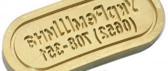
Pantograph
Photo 1: machine for cutting letters.
Used for flat threads. Its design is based on a geometric figure - a parallelogram. One of the properties of this mechanism is that the nodal points describe equidistant curves during movement. Moreover, if the link is lengthened, then its end point will travel a greater distance. This property allows the mechanism to be used for scaling.
The photo shows that the total length with the copying tip at the end is approximately 2 times longer than the side of the parallelogram. This means that the mechanism is magnifying. If you copy a shape with a tip, the cutter will reduce it by 2 times. This will reduce copier errors. Do not forget that the drawing or template is enlarged.
To make a pantograph you will need a purchased router and several dry boards. Apparently it doesn't get any cheaper.
Machine with plane-parallel mechanism
Photo 2: contour milling
Features of the use of the unit
The milling operation is one of the most common options used in material processing. A copy-milling machine for wood can perform functions such as roughing, semi-finishing or finishing processing of shaped and simple surfaces of workpieces.
This operation is characterized by its very high productivity. Thanks to this, this unit allows you to obtain parts with the correct geometric shape.
Duplicarver for wood drawings
Contact numbers/Whatsapp:
+7 +7 +7 E-mail Our VK group: vk.com/duplicarver
We present the third version of the copy-milling machine “Duplicarver-3”.
Created on the basis of the Duplicarver-2 machine, it retained all its capabilities and acquired completely new ones.
Now it is possible to produce long volumetric threads.
The maximum diameter of the product is about 30 cm, and the length is not limited, within reasonable limits, of course.
The most common carving objects would be gun stocks, table legs, stair rail balusters, long lamps, tall figurines, and any other objects that are sized to fit the working capabilities of the machine.
The photo shows a copy of the IZH27M hunting rifle. The product is made of solid alder board. Length 1100 mm.
But if you need to do sculptural carving, simply remove the long carving kit and get started.
Thus, “Duplicarver-3” is a universal copy-milling machine, perhaps unparalleled in its capabilities and, most importantly, in price.
The machine is equipped with 1180 mm guide pipes. This size, chosen taking into account ease of shipping and transportation, is quite sufficient for most jobs.
If it is necessary to manufacture longer products, you simply need to replace the guide pipes on the machine with longer ones. These are standard aluminum pipes with a diameter of 30x3 mm, which can be freely purchased in any city at a metal depot or in a specialized store.
If such products are not available in your city, we will deliver pipes of the required length to you using a trucking company.
HOW MUCH DOES DUPLICARVER-3 COST?
For any questions, call +7-911-984-69-18.
We can deliver Duplicarver-3 to any city in Russia. Delivery to Belarus, Kazakhstan, Armenia and Kyrgyzstan is also possible. Read the terms of delivery and payment, and fill out the order form. We will contact you to clarify all details and issue an invoice.
SPECIFICATIONS:
Sculptural carving:
Flat relief carving:
Long volume thread:
Milling methods
In order to carry out this process, you can use one of two existing methods:
- The first method is the counter milling procedure. When using this method, the feed of the element is opposite to the movement of the cutter.
- The second method is down milling, the essence of which is that the part and the cutter move in the same direction.
Currently, materials such as mineral ceramics, synthetic, and superhard are used as materials for the manufacture of cutters. However, it is worth saying that the use of such high-quality substances for the manufacture of cutters can replace the grinding procedure. But this is not very relevant for a wood milling and copying machine, since the material is initially quite soft.
It is also worth noting that there are two types of such machines:
- The first group is general purpose units.
- The second category is specialized devices.
Copy-milling equipment belongs specifically to the second category of machines.
Which one should I do?
Dozens of different milling operations and at least a dozen types of machines for them are used to process materials. At home, not all of their designs can be repeated by beginners and intermediate craftsmen. 2- and 3-axis CNC machines (2D and 3D wood milling machines) are not discussed in this article. It is possible to make a 2D or 3D milling machine yourself (item 1 in the figure below), but already having quite a lot of experience working on a simple machine, a significant volume of orders and an urgent need for a sharp increase in labor productivity. At the same time, you will have to master programming microcontrollers, because... finished samples are designed for a machine of a very specific design; There will also be significant costs for stepper motors and precision drive parts.
Types of homemade wood milling machines
To begin with, at home, you can make a homemade milling machine using any of the following. varieties:
- Horizontal (item 2 in the figure).
- Vertical (item 3).
- Flat copy machine with pantograph (2D duplicator, item 4).
- Machine for volumetric copying (3D duplicator, item 5).
Tool…
The choice of a machine of one type or another is determined, of course, by the work operations most used by the master. To specify their nomenclature, you must first decide which working parts (cutters) you will most need. Most of them are applicable in both horizontal and vertical machines.
Types of wood cutters
Mounted cutters (item 1 in the figure) are processed primarily. straight edges of the boards: grooves and ridges (including shaped ones) are cut out to their full length, and a chamfer is applied. The spindle assembly of the machine for attachment cutters (see below) is structurally the simplest; its parts can be turned by a 3rd class turner. The required drive power for a processing depth of up to 60 mm is from 1.5 kW. The quality of the material is almost any, ranging from raw material straight from the sawmill. A vertical wood router is most suitable for attachment cutters, see for example. Below is a video in 4 parts:
Video: homemade wood milling machine with attachment cutters
There are many more varieties of milling cutters with a cylindrical shank (landing, seating), because their functionality is wider. But for such a cutter it will be necessary to machine a spindle attachment with a Morse taper for a clamping chuck; It is also possible to use ready-made spindle units from a drilling machine.
End mills, e.g. Forstner cutter (item 2 in the figure above) is a specialized tool; They choose round holes with a flat bottom in thin boards with a decorative coating that cannot be damaged. Have you ever hung doors on furniture? The holes for their loops were chosen using a Forstner cutter. The quality of the material is no worse than straight-layered wood of the 1st grade, chamber dried. Required drive power from 150 W. They work with end mills only on a vertical machine or, with a certain skill, manually.
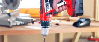
Note: using a Forstner cutter in a 170 W screwdriver to select holes D32 for door hinges in furniture chipboard 16 mm thick is quite possible, I did it myself.
End (finger) milling cutter, pos. 3, can be threaded into both horizontal and vertical spindles. Using end mills, blind grooves are selected (not the entire length of the board) and tenons are cut for tongue-and-groove joinery joints. It is more convenient to work with an end mill on a horizontal machine. On a vertical surface, it can be used to select long grooves (grooves) of a rectangular profile on the surfaces of boards and beams. Tapered end mills (item 4) are also a specialized tool for preparing parts for dovetail joints. They work with conical end mills only on a vertical machine. For both of them, the required drive power for a processing depth of up to 80-100 mm is from 1 kW. The quality of the material is from commercial wood of the 2nd grade, air dried (from a timber exchange).
End shaped (curly) cutters, pos. 5, also a specialized, but highly sought after tool. They apply molding (including on curved edges) and select shaped grooves (decorative grooves) of any configuration in the faces of the boards. Drive power from 1.2-1.5 kW; The quality requirements for the material are the same as for end mills. To process edges, the shaped cutter can be threaded into either a horizontal or vertical spindle; for working on layers only in a vertical position.
Roller-cone cutters (burrs, item 6) can also be used to select shaped grooves and create a groove on both a horizontal and vertical machine, but in general they are a special tool for copy milling machines. The requirements for the quality of the material are high, as for end mills, but the drive power in the copier can be from 250-300 W.
And, finally, using a circular cutter (item 7) in a vertical milling or drilling machine, round holes of large diameter are cut out in almost any material that is not overly thick (including sheet metal). Required drive power per hole D200 in 60 mm thick oak board approx. 2-2.5 kW.
...and his presentation
Milling can be done in two ways: up and down, see fig. below. As for wood, ordinary straight-layered wood (especially one that is not of very high quality air-dried) is milled only along the way, otherwise the milling cutter can even split and/or fray the workpiece. But in this case, with an excessive feed rate, there is a considerable probability of the workpiece being pulled away by the cutter and damage to the processing profile. Removing dust, sawdust and shavings from the working area (and this is a serious problem) on a vertical milling machine during down milling is difficult, because The dust collector (see below) has to be placed in the field of view in front of the cutter and it obscures the working area.
Up and down milling methods
Note: on a horizontal milling machine there are no problems with removing processing waste during down milling, because dust (sawdust) then flies down, and the dust collector socket can be placed directly on the machine plate (see item 2 in the figure at the beginning and below).
Up milling gives better precision and cleanliness of processing, but only on sufficiently high-quality and homogeneous materials. From wood - on solid, fine-grained wood, chamber dried. Removing processing waste on a vertical milling machine is easier, but on a horizontal one it is difficult - dust and sawdust fly upward. The removal of the workpiece is almost impossible, but there is a danger of it being bitten by the cutter. A well-behaved profile can often be modified; a bitten and broken piece is an unconditional defect.
Motor
Based on the above, it is optimal to make a do-it-yourself milling machine with a drive with a power of 1.5-2 kW. The reason is that motors up to this power are produced, incl. asynchronous with capacitor starting for voltage 220 V 50 Hz. They can be plugged into a regular household outlet, and switching the direction of rotation is a child's task for an amateur electrician; rotation speed is 700-2850 rpm, which is suitable for milling. It is also possible to use an electric motor of the same type from a washing machine; in this case, it becomes possible to switch the rotation speed (in asynchronous washing machine motors there are different windings for this). A 2 kW motor will provide a processing depth of up to 80-100 mm; if a larger one is required, you will have to install a three-phase motor at 380 V 50 Hz from 3 kW into the machine, see for example. video clip:
Video: homemade vertical milling machine for wood
Note: commutator electric motors of 1.5-2 kW 220 V 50/60 Hz (for example, from another washing machine or vacuum cleaner) are of little use for driving a milling machine - due to their excessively soft external characteristics, the cutter may get stuck in the wood if the workpiece is not manually fed, tear and rag it (if it’s damp).
General description of the copy-milling device
A wood milling and copying machine is used to perform copying-type work in volume as well as on a plane. In addition, the device is also used for work using three-dimensional models. To perform such operations, appropriate copiers are also used.
This unit can also be used to perform engraving operations, applying patterns, ornaments or various inscriptions. The greatest advantage of a wood milling and copying machine is that, with its rather simple structure, it is capable of performing a large number of different complex operations.
Work methodology
The tracking systems and the working element can be connected to each other using pneumatic, hydraulic or mechanical elements, which are required to generate the force from the copier to the working element. The template can be a flat contour or spatial model. You can use contour drawings, a reference part, but the element for reading the dimensions and shape will be a copy roller or finger, photocells or a probe.
You can use wood, plastic or metal for the template. This unit must be located on a rotating work table of the equipment. When CNC milling and copying machines are manufactured, they must have an end-effector that is driven by a solenoid, spool valve, or magnetic clutch. Relays are located in amplifying devices; they can be hydraulic, electromagnetic or electro-optical.
The essence of the work
It should be noted that the ability of the device to work with various materials depends on the alloy from which the cutter is made. Operations can be carried out not only on wood, but also on steel, cast iron, and non-ferrous metals. To do this, it is necessary to use carbide as the material for the cutter, as well as provide a high number of revolutions per minute. These types of units can be used both for large-scale production and for the production of small batches.
For example, such devices can be used to produce things such as ship propellers, turbojet engines, steam turbines, various shapes, molds, and wood blanks.
It is worth noting that models of a CNC copy-milling machine for wood are produced. The purpose of this type of device is to perform the milling operation of curved parts. To perform such a task, these machines use a pattern copying method. The use of this method helps eliminate the human factor. This is very important, since a person is not able to create two perfectly identical things, unlike a machine. As a result of the mechanization of the process, that is, the use of machine tools, it became possible to conveyor production of various parts and elements with a curved shape and absolutely identical dimensions.
Copy model CL-1201
To produce wood products, a machine model CL-1201 or CL-1500b can be used. The first version has very attractive performance characteristics:
- The spindle used can change the direction of rotation. Due to this, the scope of application of the model is significantly expanded. Changing the direction of rotation of the spindle is carried out with a special handle.
- The machine allows you to select the spindle rotation speed with high precision. Due to this, it is possible to provide the most favorable conditions for turning wood based on the weight, dimensions and type of wood.
- There is a remote control to set basic parameters. The design can be installed on the headstock or tailstock, depending on the preference of the master. The remote control is represented by a combination of several keys.
- Cast iron is used in the manufacture of the column. In addition, the frame is manufactured using high-quality steel. By combining these materials, the degree of vibration of the structure during operation is reduced.
- The basic delivery includes a copier, which can be used for processing. Due to this, costs are reduced and the machine becomes more functional in use.
- The design of the machine has a milling attachment, which can be used to produce longitudinal grooves.
- The tailstock is used for more precise fixation of the workpiece. Its position may also change. The supply includes centers, which are selected depending on the characteristics of the workpiece.
- The support is characterized by high mobility. The cutting depth of the tool can be adjusted using a lever.
In addition, the manufacturer paid quite a lot of attention to the degree of protection of the machine from environmental influences. For example, the engine has a protection system against overheating or overload, all electronic parts are also protected from moisture and dust.
The only but significant drawback is the high cost of the proposal. A homemade design will cost several times less.
DIY machine
Today it is possible to purchase such a device on the market. However, the possibility of creating a homemade wood milling and copying machine cannot be ruled out.
Since there are quite a few designs of this equipment, its typical, most common form will be presented.
The components of such a unit are as follows:
- working surface;
- supporting frame or bed;
- milling head.
It is important that the working surface of the equipment has the ability to be adjusted in height, and that the milling head is equipped with an electric drive. In addition, a two-stage mechanism must be connected to it, the task of which is to provide two different speed levels of the milling head.
A fairly common disadvantage of homemade devices is that they are not able to create an exact copy of the product. The reasons for this are most often trembling, vibration, as well as a change in the direction of the cutter. It will not be possible to avoid all flaws, and therefore, in order to minimize their presence, experts recommend creating a narrowly focused equipment model, rather than trying to make it universal.
Classic machine design
The machines are equipped with a sophisticated design system. These include CNC models that operate in an automated mode. Such devices are obtained by using drawings and a copying device. The classic design consists of five nodes:
- The main element is a metal frame; individual parts are connected by welding. The bed has different heights, so when creating a homemade machine, this particular parameter is selected.
- The front and tailstock are needed to store the box, drive and electric motor. The rear one fixes the workpiece to obtain dimensional parts.
- An electric motor and drive rotate the workpiece.
- A tool rest is needed for the best quality work. The cut site is protected to prevent injury.
- The master and slave centers secure the part.
A homemade lathe-copier for wood makes it possible to carry out high-quality cutting of workpieces no worse than production models.
Recommendations for creating a machine
When making a copy-milling machine for wood with your own hands, you need to create a drawing and design all the parts in such a way that in the future it will be convenient to work with workpieces of the selected size. For example, there are two types of work - milling long workpieces or engraving. These two operations require that the method of fastening the workpiece, as well as the work surface, be completely different.
This is not the only reason why you need to think things through in advance. The second thing that anyone who creates a machine on their own will have to face is the choice of an electric motor. Depending on the density of the material with which you will need to work, it is necessary to select the power of this product. If we talk about working with wood, then most often a motor with a power of 150 to 220 W is enough.
Another feature that must be observed is the most durable fastening of the copy probe and the device that holds the cutter. These two small details are very important, since the accuracy with which the machine can reproduce the model from the sample will depend on this.
Duplicarver for wood drawings
Contact numbers/Whatsapp:
+7 +7 +7 E-mail Our VK group: vk.com/duplicarver
We present the third version of the copy-milling machine “Duplicarver-3”.
Created on the basis of the Duplicarver-2 machine, it retained all its capabilities and acquired completely new ones.
Now it is possible to produce long volumetric threads.
The maximum diameter of the product is about 30 cm, and the length is not limited, within reasonable limits, of course.
The most common carving objects would be gun stocks, table legs, stair rail balusters, long lamps, tall figurines, and any other objects that are sized to fit the working capabilities of the machine.
The photo shows a copy of the IZH27M hunting rifle. The product is made of solid alder board. Length 1100 mm.
But if you need to do sculptural carving, simply remove the long carving kit and get started.
Thus, “Duplicarver-3” is a universal copy-milling machine, perhaps unparalleled in its capabilities and, most importantly, in price.
The machine is equipped with 1180 mm guide pipes. This size, chosen taking into account ease of shipping and transportation, is quite sufficient for most jobs.
If it is necessary to manufacture longer products, you simply need to replace the guide pipes on the machine with longer ones. These are standard aluminum pipes with a diameter of 30x3 mm, which can be freely purchased in any city at a metal depot or in a specialized store.
If such products are not available in your city, we will deliver pipes of the required length to you using a trucking company.
HOW MUCH DOES DUPLICARVER-3 COST?
For any questions, call +7-911-984-69-18.
We can deliver Duplicarver-3 to any city in Russia. Delivery to Belarus, Kazakhstan, Armenia and Kyrgyzstan is also possible. Read the terms of delivery and payment, and fill out the order form. We will contact you to clarify all details and issue an invoice.
Milling and turning copying machine for wood
The purpose of this type of machine is the processing of wooden products, turning profiles and decorative blanks. A distinctive feature of this type of equipment is the presence of two cutters at once. One of them is mounted on a steady rest and is intended for processing round wood blanks. This cutter is capable of removing up to 10 mm of material in one pass of the part. Settings for this element are configured on a special device.
The second cutter is mounted in the copy carriage, and its main purpose is to turn workpieces according to the sample. In order to ensure comfortable work with long elements, the unit has a steady rest that can be attached to the guide rod. It is used as the main support to prevent the long workpiece from bending. It is also possible to install a part such as a faceplate. This allows you to process parts with a large number of edges.
Features of manufacturing copy-milling turning equipment
The copy milling and lathe machine will work, providing quality depending on the speed of movement of the follower. The actuator circuit will have a main element in the form of a hydraulic cylinder or an electric motor. The guide pin will make up the pantograph structure. It is necessary to place the guide pin and spindle on the same rail.
The lath must have shoulders, the ratio of which will determine the scale of copying. A copy milling lathe will have a finger that will move along the contour of the templates. He will be responsible for the movement of the rack, which rotates freely on the axis. On the other side of the rack, the spindle will make identical movements when processing parts. On such machines, the described device will not be superfluous, and its presence will increase functionality.