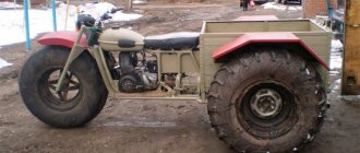
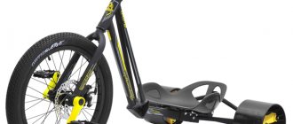
Good afternoon everyone! In this review we will talk about perhaps my most exciting DIY project, which brought such a lot of positive emotions to both children and their parents. We will make a children's tricycle (trike) from an old Chinese mini-Segway/hoverboard and a children's bicycle. As always, in the review I will present in detail the available components and components used, the process of manufacturing and assembling the design of a tricycle with rear suspension, preparing and installing electrical components, setting parameters and firmware of the motor-wheel controller for comfortable riding and control. The review turned out to be quite voluminous, I tried to present all the main points and features of the implementation of the task, so I will have to allocate considerable time to familiarize myself with the material in detail.
I will immediately ask mechanical engineers, electrical engineers and programmers to forgive me for errors in the terminology I use, I am just trying to understand this, please treat it with leniency, as a review from a construction linguist).
INTRODUCTION.
The idea to implement this project arose when our mini-Segway called “A8,” which is already 4 years old, broke down once again.
The Segway stopped responding to turning the handle, and accordingly the rotation function disappeared. It was necessary to deal with the Hall sensor, but to be honest, I no longer had the desire to do this. The Segway had already begun to show signs of inappropriate behavior: it switched off several times while driving, tilted excessively backwards when accelerating, and it was already becoming dangerous to ride. Therefore, the idea was born to use its motor-wheels and make a tricycle as the simplest design. Having gone online to develop the idea, I suddenly realized that everything had been happening for a long time without me, and my idea had long been worked out by a large number of people). Therefore, before direct implementation, I familiarized myself with the experience of other home-made people, and noted the following main points for myself:
— the tricycle must have a rear suspension, since we live in the private sector, and we do not have smooth asphalt roads near our house (maximum dirt roads rolled with asphalt chips), and driving onto the city roadway is not entirely correct; — the tricycle should be a two-seater, since we have two children, and organized alternate riding, sooner or later, will still lead to loud conflict and complaints; — the tricycle must be assembled on a native controller from a Segway/hoverboard, since many enthusiasts are working on open firmware for boards on STM32/GD32 microcontrollers, which are installed in these Chinese products. It becomes possible to get software fixes, flexible settings, and additional functions, unlike ready-made Chinese controllers for electric vehicles.
The ideological inspiration for my tricycle was the work and videos of the author of the Youtube channel ILYANOV. He developed his own tricycle design, and also made his own alternative firmware for the hoverboard controller for convenient control as a tricycle. It has a free (with maximum speed limitation) and paid firmware version. The amount for paid firmware is more symbolic, but I soon came across other alternative firmware options online, with more flexible configuration and more efficient operation of motor wheels. More on this later. I’ll say right away that I borrowed the idea of the rear suspension from my friend ILYANOV, as a simple and affordable option, but I did not use the frame of the hoverboard itself in my design.
During a short simulation, the following tricycle design was obtained and agreed upon with the children:
What do we need?
Before you make a hoverboard, you will need to collect all the necessary parts and make accurate calculations.
The summary list of materials (with recommended grades) is as follows:
- XBee wireless control module.
- Arduino microcontroller.
- Battery - 2 pcs.
- Inven Sense MPU-6050 sensor on the GY-521 module (can be replaced with another brand with similar or similar characteristics).
- The material for the body and handle is thin steel or wooden beam.
- Wheels with a diameter of 26 cm.
- Switch.
This minimal set will help you assemble a Segway with your own hands. You will also need the appropriate tools depending on the housing material. In terms of cost, it is best to make it from wood, but it is possible to use aluminum. You will need to prepare a blowtorch with all the necessary accessories, a drill, a set of wrenches, a hacksaw (for working on metal or wood), pliers and a simple measuring tape.
ACCESSORIES:
To manufacture and assemble the tricycle, I purchased the following components and materials:
ST-Link V2 programmer
. We will use it to load new firmware for the STM32/GD32 microcontroller on the Segway/Hoverboard board. Link: ST-Link V2 stlink mini STM8STM32 STLINK simulator download programming With Cover
A set of handles for a bicycle handlebar, with an accelerator handle on a Hall sensor,
with an integrated voltmeter to monitor the battery voltage, and two buttons: a latching button (red) and a non-latching button (green), which we will use as an electronic brake button. Link: Electric Bike Voltage Display 1 Pair Universal LED Voltage Display Twist Throttle for 12-99V Ebike Scooter Durable
Tires and inner tube for a car, size “6” - 4.00.” Since the original tires of the motor-wheels are low-profile, more suitable for smooth asphalt, and they cannot reach high speeds, it was decided to change them to tires with a larger outer diameter. Buy something special from Kenda, 2-2.5 tr. There was no desire for a tire yet (there was no complete confidence in the success of the ongoing project), so a cheaper option for Delta tires was considered in the online store. Tire link: Delta 400-6 tire for pneumatic wheel Link to tubes: Tube 400-6 for pneumatic wheel
To make a shock-absorbing rear suspension, we purchased the simplest bicycle shock absorber with a declared stiffness of 850 LBS, which in the end turned out to be not enough, although the shock absorber may not correspond to the declared stiffness. Link: Rear frame shock absorber KZ-880B, 165 mm/420030
To make the frame of the tricycle, the following steel profile was purchased:
- Profiled pipe 20x20x2 – 3m;
- Profiled pipe 40x20x2 – 3m;
- Profiled pipe 40x40x3 – 1m (was in stock);
- Plate 40x4 – 1 m (cuts were available);
Also purchased at an auto parts store:
- Medium jet rod 2101-07, link: Jet rod
- Rear shock absorber bushing 2101-07 large metal spacer, link: Shock absorber bushing
We also purchased a high-strength M12x170 bolt with a short thread (for fastening the subframe) from a fastener store. A
used children's bicycle was purchased as the front part of our tricycle. When searching, the priority was the presence of a front hand brake:
Segway repair
Repairing the Sibway came down to replacing the power transistors, their drivers, and piping resistors. The burnt-out track was also restored, the lock and key were replaced with ordinary toggle switches, and a 63 A circuit breaker was included in the circuit. I hope, if something happens, it will save the circuit from burning out.
Only in this case will someone’s nose suffer again.
So the forecast is pessimistic, buy only quality items, especially when it comes to safety! Now it’s clear why all the photos show a Segway rider with a helmet on...
MANUFACTURE AND PREPARATION OF MAIN COMPONENTS AND ASSEMBLY:
First of all, it was decided to start production by preparing the wheels and rear axle of the tricycle.
The wheel motor was clamped in a vice and the tire and tube were replaced. The hole for the nipple in the aluminum wheel rim had to be slightly drilled out with a 9mm drill, since the base of the nipple on the new camera was noticeably thicker:
The result was these impressive bagels:
It was decided to use a 20x20x2 profiled pipe as the rear axle. The diameter of the axle of the motor-wheel itself is 16mm, and I previously tested on a small piece of material how the square profile fits on the axle. There was a small play of 1 mm, but given the planned tightening of the axle in the profile with two bolts, this play suited me. Then I bought 3 meters of a new profile, and now it fit the motor-wheel axle just perfectly, it even had difficulty getting into tension, it turned out even better than I expected.
Accordingly, I cut off a piece of the profile for the future tricycle axle and prepared the nuts and bolts for fixing the motor wheels:
I drilled holes in the profile and estimated where to attach the nuts:
I welded the nuts and tightened the bolts:
I prepared holes for the output of wires from the motor wheels and assembled the finished rear axle:
The rear subframe was made from a 40x20x2 profile, made cuts in the profile and bent the shape of the future subframe in a vice:
I welded the internal jumper of the subframe and welded all the joints:
I took the purchased reaction rod with silent blocks, cut it in half, fastened both halves with an M12x170 bolt through a spacer sleeve, marked it and welded it to the subframe structure. Note: I'm still a welder! Experienced people know, but I did not immediately realize that when actively laying welded seams, it is necessary to take into account the thermal expansion of the elements; accordingly, the subframe jumper where I welded the halves of the rod became hot, it had nowhere to expand, and it went in a slight arc. It didn’t play a special role, but the moment was not very pleasant.
The spacer sleeve turned out to have a slightly larger internal diameter than expected - 16 mm, but it was not possible to find a smaller diameter. Therefore, I proceeded in the same way - drill a hole, weld a nut and fix the axle in the bushing with an M8 bolt:
We place our resulting subframe and try on a square frame profile, grab and weld the bushing to the frame profile:
We connect the frame profile and the subframe, use a bolt, washers and an M12 nut:
To attach the subframe shock absorber, I prepared plates from a 40x4 strip and made 8mm holes. I made several holes for possible replacement of the shock absorber and changing its position:
We set the angle of inclination of the subframe to the frame and try on the plates with the shock absorber, cut the plate to the desired angle for attaching to the subframe pipe and weld it:
We prepare the shock absorber mounting mate from a piece of 20x20x2 profile and plates with an 8 mm hole:
We try on the shock absorber response bracket to the frame, cut it and weld it. I’ll say right away that I then had to cut it off and cook it a little further, because I laid the angle of the subframe to the frame too small, and even with a small load the subframe came out flush with the axis of the frame:
I prepared and welded the rear seat mounting plates, with 8 mm holes:
Likewise the front seat plates:
To continue the work, it was necessary to make the seats themselves, because the place of attachment of the footpegs for the driver and passenger, as well as the point of attachment of the front part of the bicycle to the frame of the tricycle, depended on them.
I cut out the bases of the seat and back from 12 mm plywood with a jigsaw (this time not on a sawing table, since he lost a saw for working outside):
Marked the mounting holes and hammered in the M8 mustache nuts
The foam rubber left over from making the bed (40mm + 10mm) was glued to the bases:
A few years ago I bought a piece of black faux leather on sale at a leather store, which I decided to use for this project. We cover the bases of the chairs with leather using a furniture stapler:
I subsequently painted the lower part of the plywood base of the seat with black paint, but for the back part of the back it was decided to make a panel from 6 mm plywood and also cover it with leather:
I made the seat frame from a 40x20x2 profile, made a cut, bent it at the desired angle, welded the joints, marked and drilled 8mm holes for fastening to the brackets on the tricycle frame:
It's time to dock the front of the tricycle. We cut the children's bicycle, place the frame on the block, shape the pipes of the bicycle frame to fit the tricycle frame, call the children and measure the required mounting distance from the seat, weld the parts:
We fasten the rear axle to the subframe with M8 bolts, drill holes and fasten:
I made the footrests for the driver and passenger from 20x20x2 pipes and 40x4 plates. We fasten with M6 bolts:
I planned to place the controller board and the tricycle battery in the subframe itself; for this, the profile height of 40 mm was not enough, and I extended it down to the level of the rear axle with a 20x20x2 profile, for a total compartment depth of 60 mm:
I decided to make the upper and lower compartment covers from plexiglass:
I fastened the covers using M6 bolts and cut the threads with a tap directly in the subframe profile:
We take all the parts of the tricycle and send them to prime and paint:
To close the ends of the profiles, I purchased end caps for the profile, and before painting I used a primer for plastic:
I sanded the “engine” compartment cover with 120 grit and also sent it for painting:
The elements of the frame and subframe were painted orange; black was chosen for the seats, covers of the “engine” compartment and the transition of the front part from the bike to the frame:
While the primer, paint and varnish are drying, we can take a break again and move on to the electronic part of our vehicle.
Even before the launch of the project, I received the ST-LINK V2 programmer and downloaded the firmware from the author ILYANOV through the STM32 ST-LINK Utility program (https://www.st.com/en/development-tools/stsw-link004.html). Everything worked out. At this link you can find the author's firmware files and his connection diagrams: link. But later I discovered an alternative firmware from another author, which will be discussed further.
For this project, only the main Segway/Hoverboard is used, additional gyroboards are folded out. There is a good picture on the Internet with the designation of all I/O boards:
In accordance with the existing components and the board, the following connection diagram was obtained:
My board is based on an STM32F103 microcontroller. I took the required +3.3V voltage from the body of the AMC1117 converter with a separate wire, which I connected to the common wiring harness from USART2 (on USART2 itself there is only +15V, which cannot be used):
To ensure that the USART2 ADC lines are not subject to interference, as well as to protect against inadequate response of the board to a wire break from the accelerator or brake handle, it is necessary to bypass the ADC2 and ADC1 pins with a 0.1-0.01 μF capacitor and pull up with 2-μF resistors. 10 kOhm to GND. I didn’t have SMD parts, so I used regular pins, and the smallest capacitor I had was 2200 pF, which also worked. Without capacitors, even my wheels began to spin briskly when I simply touched the housings of the motor wheels with my fingers:
To install resistors and capacitors, we had to remove the heatsink from the board and put it back. Pay attention to the protruding red wire on the side of the board (circled in red).
This is exactly the +3.3V wire that I added. During the rotation of the board when installing the radiator, this +3.3V wire came into contact with the radiator body as a bare conductor, and a short circuit occurred. The capacitors on the board were not discharged, and I shorted +3.3V. The result was not long in coming - the board does not work. At first I thought that the +3.3V AMC1117 power converter had failed, since it only had 1.2V when power was applied, but after replacing it (I took it from the gyroboard) nothing changed. Upon further diagnostics, it was discovered that the STM32 chip was dead, short circuited. There was no limit to disappointment. I had read before that when performing any manipulations with boards, it is necessary to discharge the capacities, especially since on this board this is done by simply holding down the power button, but for some reason you remember about this when everything is already bad. So much work has already been done, and that’s it, there is no payment.
The next morning, several hoverboard repair shops were called, and the price for a used hoverboard board was received - 2000 rubles. And a little later, a small search on Avito produced several results for used hoverboards in the city at a similar price. By evening, a whole hoverboard was purchased, with a non-working battery, for 2000 rubles.
As a result, I ended up with a board, a non-working battery (6 of the cells in the battery were dead, the other 14 were with a voltage of 3.5-3.8V), and a set of new motor wheels for the next project. On the old board it is necessary to change the microcontroller chip, but there is no soldering station-hair dryer available, only T12, and there is no experience yet.
The new board turned out to be based on the GD32F103 chip, which initially alarmed me. But according to reviews from enthusiasts, it is also flashed with the same firmware as the STM32. Now I can say that there are no problems with compatibility. Also, on this board the mosfets are screwed to the heatsink with nylon screws; on the red board there were steel screws with plastic bushings-washers:
The board was placed on the base of the “engine” compartment on stands made of screws, nuts and M3 washers
To switch all the incoming lines from control devices, power buttons and the charging connector to the board, I decided to make just such a small board with screw terminal blocks. There is also a variable resistor on the board, which I planned to use to regulate the strength of the electronic brake, because I use a simple button for the brake with two values 0% and 100%. In practice, it turned out that a variable resistor is not needed, and you use the electronic brake only when the front manual brake is not enough, and maximum brake efficiency is only welcome.
To connect the wires from the battery, fuse and battery disconnect button, I used small feed-through terminal blocks on a mini-DIN rail.
I purchased a fuse holder from a car store to protect the battery from various troubles:
I placed the switching board and DIN rail with terminal blocks on the base:
I placed the battery accordingly, secured it with a standard clamping part, painted the base on the reverse side with black paint, and connected everything:
Place the base on the subframe:
We screw the rear axle of the tricycle and connect the phase wires of the motor-wheels and connectors from the Hall sensors:
Electronic filling of the Segway
Now let's take a closer look at the electronics of the Segway.
Here is a photo of the control board connection.
Larger device and board connection
Power transistors – IRF4110:
Power transistors of the control board
It was a couple of these transistors that burned out. At the same time, this pair short-circuited the battery power, forming a short circuit.
Segway electronic circuit - general view
Let's look at the elements of the circuit in more detail.
Electronic circuit of a Segway - general view - another angle
The circuit in general is not large, we will divide it into several parts - a receiver, a controller, an electronic gyroscope, transistor drivers, power transistors, and a power supply.
Microcircuits IC3, IC4 are a radio channel that allows you to control the Segway from the remote control. That is, configure it, calibrate it, block it, diagnose it.
Chip IC2 is an ATMEGA 32A controller. This is the heart of the Segway, or rather, the brain. The most important thing is contained here - the program, the algorithm of work. It is this program that controls the rotation of the wheels and prevents a person from falling.
If the controller is the brain, then the gyroscope is the sense organs. The gyroscope is a small INVENSENCE MPU6050 chip. This remarkable device is a three-channel position meter (tilt along three axes) and a three-channel acceleration meter. If anyone remembers from physics, acceleration is the rate of change of velocity. Honestly, I don’t understand how such meters can be crammed into this chip. I still knew electromechanical gyroscopes, but only electronic accelerometers. Now I found out that there are such things, and they are used very widely, mainly in mobile and automotive electronics.
The last photo also shows two CD4001 buffer chips (this is 2I-NOT). This is for decoupling the controller and the rest of the circuit. Next, the control signal goes to the IR2184S drivers, which supply voltage to the gates of the power field devices, the photos of which I gave above.
The XL7015 power supply is a DC-DC converter; from a floating DC voltage of about 48V, it produces a stable DC voltage of 15V by converting at a frequency of several kilohertz. Next, a regular Krenka 7805 produces 5 Volts. There was a yellow clumsy jumper, I had nothing to do with it. But the burnt track at the top right is the 0V power path for control, it had to be restored.
The low-current elements of the Segway circuit are connected via a backplane:
Signals come to this board: from the steering wheel potentiometer, from the person presence buttons, to the control panel LEDs. And the wires go to the main board.
Here is an engine with gearboxes, on the axles of which the wheels are directly mounted. Well made, just no markings:
Wheel motor with gearbox
The battery also does not contain any inscriptions:
Battery 48V
Includes two charging wires (thinner) and two output wires.
Do you see the distorted places? The battery is not secured at all, dangles in the Segway, and hits the sharp edges of the stiffeners.
In general, it was made poorly... in short, it was poorly made, and one way or another, the early breakdown of the Segway was inevitable.
Another gadget - a converter, was also lying at the bottom, wrapped in film. Since the side light LEDs are designed for a voltage of 12 V, and the battery is designed for 48 V, a DC-DC 48-12 V converter is used:
Sibway diagram
ASSEMBLY:
We take everything outside and start assembling the tricycle. We connect the frame and subframe:
The bolt for fixing the subframe mounting axis in the spacer sleeve was placed on the thread lock:
I secured the M12 nut of the subframe axle using the old method: I drilled a 3mm through hole through the nut and M12 bolt, inserted a nail and bent it:
We install the shock absorber. For fastening, I use nuts with nylon inserts everywhere so that they do not unscrew while moving:
We attach the driver and passenger footrests:
We assemble the seats and place them on the frame, also fastening them with M8 bolts:
We put new handles on the steering wheel:
To install the power button, battery charging socket, battery disconnect button, I decided to use a black terminal box with rubber membranes for cable input/output:
Placed the power button and charging socket:
To attach the terminal box to the frame, I placed a metal plate on rivets, and secured the box itself to it with bolts and nuts:
I ran a cable from the accelerator handle through the box, it will transit to the subframe, as well as corrugations for laying two lines: a 3x2.5 mm2 power cable for the battery shut-off button (and in the future two batteries), a 3x2x0.5 mm2 control cable for the power button, charging sockets and 2 wires in reserve. Cable 3x2.5 in one corrugation 16mm, cable 3x2x0.5, and cable from the handle - in another corrugation;
For future switching of two batteries, and for emergency shutdown of the battery in case of inappropriate behavior of the tricycle, I purchased a waterproof 30A button and installed it in the terminal box cover:
To enter the corrugations into the “engine compartment” I decided to use brass cable glands. I drilled the holes with a step drill and secured them with the supplied nuts:
The result is a device like this:
Similar products
The closest product is a hoverboard. The only visible difference is the absence of a steering column, while the hoverboard is controlled by the handles. In addition, regular scooters are very similar to Segways.
Thus, you can assemble a hoverboard with your own hands. The main thing is that the total cost of parts and costs for everything else does not exceed the price of the factory model. A homemade Segway, if configured correctly, will be a great novelty in the yard and a reason to show off to your friends.
PREPARING AND LOADING THE FIRMWARE:
As I wrote earlier, as a software part, I chose the open project of the enthusiast Emanuel Feru on Github: github.com/EmanuelFeru/hoverboard-firmware-hack-FOC
This project proposes to use both sine and vector (FOC) 3-way control principles phase electric motors, with the field weakening function (Field Weakening), as a result we get very soft operation of the motor-wheels, excellent smoothness of speed and torque, as well as a higher speed.
To configure, compile and load the firmware into the microcontroller, we will use what the author of the project himself recommends - PlatformIO IDE, which is installed as an extension in Visual Studio Code from Microsoft. To be honest, I have never had to use these tools before, since I am somewhat far from programming. I did all this under MacOS, but I checked it in a virtual machine on Windows 10, everything installs and runs the same. (The only problem was when installing PlatformIO in Visual Studio Code on Windows 10, there was a cyclical installation process until I installed the Python 3.7 distribution on the system)
We open in PlatformIO (installed in Visual Studio Code) the folder with the project downloaded from Github, and open the platformio.ini file, in which we are given a choice of options for our firmware. There are many implementation and management options, but we are interested in the VARIANT_HOVERCAR option, so let’s uncomment the line:
default_envs = VARIANT_HOVERCAR ; Variant for HOVERCAR build
Then, go to the “Inc” subfolder and open the “config.h” file
In this file we will edit the parameters we need before compilation.
First of all, let's go to the “BATTERY” section, where in the line
#define BAT_CALIB_REAL_VOLTAGE 3970
We need to indicate the actual value of the battery voltage in millivolts. And in the line
#define BAT_CALIB_ADC 1492
The value measured by the controller’s ADC is entered, which we will receive via the serial port a little later.
Let's go to the “MOTOR CONTROL” section
And check the selected motor control mode in the line
#define CTRL_TYP_SEL FOC_CTRL
So that we use FOC mode
In the same section, you can disable one of the wheels if only one motor-wheel is used (otherwise the firmware, after switching on, will complain about the breakage of one of the wheels)
// Enable/Disable Motor #define MOTOR_LEFT_ENA // [-] Enable LEFT motor. Comment-out if this motor is not needed to be operational #define MOTOR_RIGHT_ENA // [-] Enable RIGHT motor. Comment-out if this motor is not needed to be operational
And also enable Field Weakening mode to increase the maximum speed of our vehicle. Speed increases significantly:
// Field Weakening / Phase Advance #define FIELD_WEAK_ENA 0 // [-] Field Weakening / Phase Advance enable flag: 0 = Disabled (default), 1 = Enabled #define FIELD_WEAK_MAX 5 // [A] Maximum Field Weakening D axis current ( only for FOC). Higher current results in higher maximum speed. Up to 10A has been tested using 10″ wheels.
I used a FIELD_WEAK_MAX of 8 because in chair testing, a FIELD_WEAK_MAX of 10 kept my wheels spinning when I released the throttle. True, this was before USART2 was bypassed with capacitors from interference. We need to try the value 10 again:
The “DEBUG SERIAL” section tells us how to obtain data from a USB-SERIAL adapter by connecting to USART3 and how to interpret the received data. We will do this after the initial firmware.
And finally go to the VARIANT_HOVERCAR SETTINGS section
String value:
#define CTRL_MOD_REQ TRQ_MODE
says that Torque Mode is used, which gives smooth acceleration, uniform driving over obstacles and uphill, and most importantly - coasting, inertial movement when the accelerator is released, without engine braking. This greatly increases the run time on the battery, since you can accelerate and coast for a certain time.
#define ADC_PROTECT_ENA
This parameter protects the system from a break in the power or GND wire from the accelerator and brake handle on USART2. The #define ADC_PROTECT_THRESH 300 parameter sets the protection threshold based on minimum and maximum values.
Due to the fact that I just use a button for the brake, which has only two values: 0 and 4095 (min/mac ADC1-value while poti at minimum-position (0 - 4095), I cannot use the protection function. Parameter ADC_PROTECT_THRESH cannot be set to less than 1, and with other values, after turning on the power in the firmware, protection is activated based on the zero value of the brake button (as if a break) and the tricycle beeps with a buzzer and does not go anywhere. Therefore, I commented out the line #define ADC_PROTECT_ENA, disabling the protection, especially that I already have hardware protection, in the form of installed pull-up resistors on USART2;
Strings
#define ADC2_MIN 660 // min ADC2-value while poti at minimum-position (0 - 4095) #define ADC2_MAX 2063 // max ADC2-value while poti at maximum-position (0 - 4095)
and the same for ADC1, you don’t have to touch it, since the author has implemented an automatic calibration mode for the maximum and minimum voltage values from the accelerator and brake handles when you press the power button on the board for more than 5 seconds, which we will do after flashing the firmware.
And here are the lines
#define INVERT_R_DIRECTION // Invert rotation of right motor #define INVERT_L_DIRECTION // Invert rotation of left motor
turned out to be very useful, because when assembling the tricycle, I mixed up the left and right wheels, and they spun in the opposite direction. This parameter for inverting the direction of rotation of the motor-wheels made it possible to correct the direction of rotation without recommutation.
String
#define SIDEBOARD_SERIAL_USART3
must be commented out. The author of the project uses one side board of the hoverboard with his own alternative firmware to indicate the battery charge using a block of LEDs. If the board is not connected, but upon startup the firmware buzzes that there is a problem and refuses to move on.
And here is the line
#define DEBUG_SERIAL_USART3
On the contrary, we need to uncomment it, since this will give us the opportunity to connect to our board using a USB-TTL adapter via USART3 and receive data on the voltage of our battery actually determined by the controller, and make an adjustment.
Line
#define STANDSTILL_HOLD_ENABLE
Helps activate the parking brake function. After a complete stop and an inactive accelerator handle, our vehicle will be impossible to move; the motor wheels will resist, naturally to the detriment of the battery charge. I do not use.
After all the changes have been made, you can proceed to compiling our firmware. Click on the “PlatformIO: Build” button in the lower left corner and compile our firmware according to the selected option and parameters, look at the result of the process in the lower Terminal window:
Once the firmware compilation process is complete, we are ready to upload it to the microcontroller on the board.
To do this, I made a three-wire cable and connected the ST-LINK V2 USB adapter to the board according to the following diagram. I first soldered a comb on the board for connection:
It is recommended not to take +3.3V from the ST-LINK V2 adapter to power the STM32 everywhere, flash only with the main battery connected to the board. Although I tried this too, nothing burned, maybe I was lucky. A colleague of donBaton’s microcontroller still burned out. It's better to avoid problems.
Before flashing the firmware, you may need to remove the write protection of the microcontroller's Flash memory. Two of my boards required this procedure.
I did this using the STLINK Utility program on Windows, but it can also be done on Linux and MacOS using the OpenOCD package. This link explains this in detail: github.com/EmanuelFeru/hoverboard-firmware-hack-FOC/wiki/How- to-Unlock-MCU-flash (How to Unlock MCU Flash)
I will present several screenshots of the MCU Flash unlocking process:
After unlocking, we return to PlatformIO again, connect our cable, hold down the power button and press the “PlatformIO: Upload” button in the program. The buzzer will beep happily and the Terminal window will display information about success:
After the initial firmware, it will be useful to calibrate the battery so that the microcontroller correctly detects the supply voltage. A USB-TTL adapter is used for this. I purchased the simplest adapter for CP2102 from this link: CP2102 USB 2.0 to UART TTL 5PIN Connector Module Serial Converter
For it to work on MacOS (and most likely on Windows), you need to install a special driver: CP210x USB to UART Bridge VCP Drivers
The device was detected in the system and became available at /dev/cu.usbserial-0001
We connect the adapter to the board according to the following diagram:
We launch the virtual serial port reading window with the command in the terminal:
screen /dev/cu.usbserial-0001 38400
The following lines of data appeared in the window:
We are interested in the values in the line under numbers 5 and 6. The value under number 5 is the measured value of the ADC, and under number 6 is the conversion to the supply voltage value. The value under number 5 must be written down.
Then we turn off the tricycle with the on/off button, connect our ST-LINK V2 USB programmer again, open the “config.h” file in PlatformIO again, go to the “BATTERY” section, and in the line
#define BAT_CALIB_REAL_VOLTAGE 3762
We enter the current value of the battery voltage, measured with a multimeter, in millivolts, and in the line
#define BAT_CALIB_ADC 1585
We indicate the measured value of the ADC, which we received under the number “5” step earlier, from the serial port.
We compile our firmware again and again load it into the microcontroller of the board.
Now our firmware correctly determines the voltage of our battery, which can be checked by again connecting the USB-TTL adapter and checking the resulting voltage value under the number “6”.
Now we need to calibrate our accelerator handle and brake button. For this purpose, the author of the firmware has provided an auto-calibration mode. It is necessary to turn off the tricycle board and turn it on again by holding down the power button for 5-8 seconds. The buzzer on the board will emit an additional signal, indicating that we have entered calibration mode. Now we have 20 seconds, during which we need to smoothly turn the accelerator handle a couple of times from minimum to maximum and release. Accordingly, turn on the brake button several times and release. The order doesn't matter. After 20 seconds, the firmware itself will exit the calibration mode and all parameters of our controls (minimum and maximum voltage values on ADC2 and ADC1) will be saved. This must be done after each download of new firmware, if we make changes to it and upload a new one.
By the way, if during the auto-calibration mode we connect to the board with a USB-TTL adapter and output data from the serial port, the screen will notify us about the start of the auto-calibration mode and show the status after completion.
In principle, everything, you can go! On a short stretch of uneven dirt road I accelerated to 32 km/h; on asphalt I think it will go faster. Children have more impressive dynamics.
UPD: Reverse gear is activated by double pressing the brake button when the tricycle comes to a complete stop. The reverse buzzer sounds and you can drive in reverse. Then again, double-press the brake, turn off the reverse mode, and drive forward.
Theory
In control theory, holding some variable (in this case the robot's position) requires a special controller called PID (proportional integral derivative). Each of these parameters has a "gain", usually called Kp, Ki and Kd. The PID provides correction between the desired value (or input) and the actual value (or output). The difference between input and output is called "error".
The PID controller reduces the error to the smallest possible value by continuously adjusting the output. In our Arduino self-balancing robot, the input (which is the desired tilt in degrees) is set by software. The MPU6050 reads the robot's current tilt and feeds it to the PID algorithm, which performs calculations to control the motor and keep the robot upright.
The PID requires the Kp, Ki and Kd values to be adjusted to optimal values. Engineers use software such as MATLAB to automatically calculate these values. Unfortunately, we cannot use MATLAB in our case because it will complicate the project even more. Instead, we will adjust the PID values. Here's how to do it:
- Make Kp, Ki and Kd equal to zero.
- Adjust Kp. Too small a Kp will cause the robot to fall because the correction is not enough. Too much Kp causes the robot to go wildly back and forth. A good Kp will make the robot move back and forth quite a bit (or oscillate a little).
- Once Kp is set, adjust Kd. A good Kd value will reduce the oscillations until the robot becomes almost stable. In addition, the correct Kd will hold the robot even if it is pushed.
- Finally, install Ki. When turned on, the robot will oscillate even if Kp and Kd are set, but will stabilize over time. The correct Ki value will reduce the time required to stabilize the robot.
The robot's behavior can be seen in the video below:
Project budget and required improvements:
The main points that need to be taken into account when finalizing this tricycle design:
- Lower subframe bump stop.
After assembly and fully loaded with passengers, it turned out that the rear seat profile meets the subframe at a long shock absorber stroke - the shock absorber is too soft. After some thought, I discovered that the shock absorber can be adjusted by twisting the bottom threaded cup upward axially to compress the spring. The rigidity increased, and the seat stopped hitting the subframe cover. At first I had the idea to immediately install a rubber bumper, just in case, from the rear suspension of the Niva. But after checking out local auto parts stores, I couldn’t find one, and I soon forgot about it. I forgot in vain, since on good bumps the children were still able to find the weak points of the structure:
I quickly came up with the following bump stop/travel limiter for the rear subframe, using a bolt, nuts and an old bearing:
It works well, but it's a little annoying, so we need to think about a different implementation.
— Driver and passenger footrests
. After several days of driving the new vehicle, the paint on the running boards began to wear off. Accordingly, it was necessary to correct this. I couldn’t find anything easier and faster than covering them with a double layer of dense heat shrink:
— Battery.
This is, at the moment, the most critical moment in this project, since the original battery is already a little tired and only lasts for 5-7 km, which is quite sad. I disassembled the dead battery from the purchased used hoverboard, took out the BMS board from it, bought new batteries, and assembled a new battery. From the remaining cans of two old standard batteries, I will assemble another battery and put it as a second one in the subframe, with the ability to switch with the previously purchased key:
What else would I like to add to the tricycle:
- headlight and tail lights;
- a small mesh trunk on the back of the rear seat;
- wings for the rear wheels (I don’t know what design and shape yet);
Riding a Segway
Riding a similar original off-road Segway (in quiet mode) is shown in the video:
The video also describes in detail the technical characteristics of this wonderful device.
Let's talk about how you can use Arduino to create a robot that balances like a Segway.
Segway from English. Segway is a two-wheeled standing vehicle equipped with an electric drive. They are also called hoverboards or electric scooters.
Have you ever wondered how a Segway works? In this tutorial we will try to show you how to make an Arduino robot that balances itself just like a Segway.
To balance the robot, the motors must resist the robot falling. This action requires feedback and corrective elements. Feedback element - which provides both acceleration and rotation in all three axes (). Arduino uses this to know the current orientation of the robot. The corrective element is the combination of engine and wheel.
The end result should be something like this:
Project budget:
| № | Name | Price, rub.) |
| 1 | Hoverboard | 2'000 rub. |
| 2 | Metal. profile | 700 rub. |
| 3 | Barbell | 430 rub. |
| 4 | Foam rubber/glue/eco leather | 800 rub. |
| 5 | Fasteners | 500 rub. |
| 6 | Tires/tube | 800 rub. |
| 7 | Knob/button/terminal blocks | 950 rub. |
| 8 | Shock absorber | 650 rub. |
| 9 | Bike | 1'500 rub. |
| 10 | Paint/primer/varnish | 960 rub. |
| 11 | Programmers | 250 rub. |
| — | TOTAL: | 9'540 rub. |
That's all! If you have questions, I will try to answer. If there are suggestions for refinement and improvement, let’s discuss it together, especially since this is already the second review on this topic.
Robot diagram
L298N Motor Driver Module:
DC gear motor with wheel:
A self-balancing robot is essentially an inverted pendulum. It may be better balanced if the center of mass is higher relative to the wheel axles. A higher center of mass means a higher moment of inertia of the mass, which corresponds to a lower angular acceleration (slower fall). That's why we put the battery pack on top. However, the height of the robot was chosen based on the availability of materials
