The pit traverse is one of the most common types of lifts among owners of both their own car services, workshops and service stations, and ordinary motorists who have their own garage with a special ditch.
Traverse for pit
Its main advantages are obvious - relatively small dimensions and weight, which allows you to easily move it from place to place, ease of maintenance and operation, relatively low price and third-party maintenance costs. It is thanks to this that companies involved in the production of pit traverses are never left without income.
What is this miracle unit? Let's figure it out.
Do-it-yourself traverse lift to the inspection hole in the garage
The following solutions were used as materials.
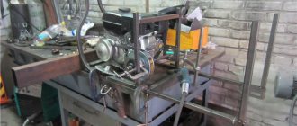
For longitudinal beams, channel No. 8 was used, for transverse beams - channel No. 6, for platforms with holes for guides - corrugated pipe 50x100. The material was selected taking into account the entry of the smaller channel with its edges into the larger one, and the profile pipe into the smaller channel, which ensures additional rigidity of the structure. Length – 500 mm, width between the edges of the cross beams – 820 mm. The distance between channel No. 6, where the pipe enters, is 340 mm. The distance between the guides is 600 mm. The length of the guides themselves is 700 mm; 32 pipes were used for their manufacture. The lifting beam is made in the form of a kind of profile pipe, which is welded from channels No. 8 and No. 6 - they are inserted into one another. The length of the beam is 1050 mm.
The jack is a two-rod jack, made in China, according to the stated characteristics - 6 tons. For the platform for the jack, 3 pieces of channel No. 6 were taken. A 6 mm reinforcing plate was welded into the end of the platform on the sides. The “wheels” are bearings 180604, size 20x52x21 - 2 pcs. on each of the corners. M20 bolts are used as axles; the part without thread has a length of at least 40 mm and a thickness of 20 mm. 30 mm spacers are inserted between the bearings and the frame. They are here because the inspection hole for which this structure is made is filled unevenly, with a floating distance between the edges. In order for the traverse to move more smoothly along the pit, horizontal guides are provided in the form of small bearings 608 (they are in the photo where the structure is placed on the pit).
also made several pneumatic traverses for a local service station a little earlier:
The device is made according to the same principle, but with some difference - with an air spring instead of a jack. A screw from a jack is welded to its body, due to which the height of the pick-up can be adjusted.
Included with the traverse were anti-recoil shoes - 4 pcs. In the shape of a right triangle, the size of the legs is 150 and 280 mm, the hypotenuse is 280 mm. Material – strip 80 mm long.
For welding, 4 mm ESAB electrodes and an industrial welding trans were used, but in some places I used P/A.
Manufacturing materials and processing methods
The vast majority of car lift parts can and should be made from rolled metal. This is convenient, because this kind of materials is available at every metal warehouse, you can purchase exactly the required quantity, and most importantly, some elements can be replaced with other types of rolled products while maintaining the equivalent section.
Some parts have requirements for primary use, so some items will have to be purchased. First of all, a profile pipe of two sizes, the thickness of the smaller one should, with a minus millimeter tolerance, be equal to the internal dimensions of the larger one, for example, 40x40x5 and 50x50x4 mm. On average, no more than two meters of each type of pipe will be required.
It is advisable to make the remaining parts from a more massive assortment: channel, T-bar or angle steel. The base of the frame can be assembled from a 14U or 16U channel by connecting two sections in parallel. The channels can be replaced with pieces of angle steel connected by a solid weld with a reinforcing lining.
At the bottom of the frame, the choice of materials is absolutely free. In total, it takes about 6 meters of 63x4 mm angle steel, but it can be replaced with almost any materials of the same cross-section. Additionally, you will need several pieces of hot-rolled steel pipe, round timber of 40X steel or similar, as well as sheet steel for making gussets.
Do-it-yourself hydraulic jack: rolling and pit (diagram and video instructions)
- How does a hydraulic jack work?
- How to make a rolling lift
- DIY pit hydraulic jack
- Bottle jack press
A strong, monolithic device that combines the unshakability of brute force with high control of the pressure exerted on the desired object. A hydraulic jack is capable of slowly and measuredly lifting loads of a mass that is prohibitive for a person from the ground, requiring minimal physical effort from the latter. In this article, we will look at how you can use the abilities of this amazing tool by making a rolling and pit lift, or a powerful utility press based on it.
How does a hydraulic jack work?
Without a clear understanding of the operating principle of the tool, it is very difficult to turn it into another device, and successfully modifying it is almost like winning the jackpot. Before moving on to the specifics of the instructions with dimensions and materials, let’s refresh our memory - what components this structure consists of, and how they interact with each other. We will analyze the principle of operation using the example of a classic bottle lift, which is the original in the category of tools of this type.
In any liquid lift, two main elements can be distinguished - a retractable piston (stop) and a housing with a cylinder that guides this stop. Hydraulic oil, flowing through the tool system like blood, performs a vital function by creating high pressure and pushing the rod out of the cylinder. Pressure is generated using a hand pump that pumps liquid from the oil reservoir into the cylinder. The movement of the liquid is controlled by special valves that allow it to move only in one direction, so that when it hits the load, it does not flow back. The main components, in addition to those listed, are clearly presented in the following diagram.
An experienced eye will immediately notice that the design of a liquid jack is quite simple and it will not be difficult to sort through such a tool. However, if you try to make a hydraulic lift with your own hands from metal plates, pipes, channels and other improvised goods, even a seasoned master will stumble upon a colossal heap of technical subtleties. In the production of such devices, special equipment is used, which is not available even in the richest garage arsenal.
It is better to purchase such a bottle-type device new or on bulletin boards and metal stores, where they are sold for pennies. Repairing a Soviet jack is not difficult, and it can already be used as a basis for creating new devices.
DIY rolling jack
Not every rolling jack can boast of good strength indicators. Models from the budget segment sometimes even resemble crafts made from cans, which should absolutely not be used without safety stops. When the original bottle lift is not suitable in height or has limited functionality, it can always be upgraded into a reliable rolling jack. The work is not easy, and in addition to powerful materials, it requires serious tools, however, if you have basic skills and desire, this task is doable.
Listed above are the main, necessary tools, without which it is not possible to make a reliable hydraulic jack. In addition to the main set, more ordinary devices available in the arsenal of anyone who has decided to assemble such serious equipment can also help with the work.
The basis for attaching the front wheels is optionally made from scrap materials. The author welded from a corner 50x50x5, 180 mm wide. The overhang is made from ordinary plates cut from the same corner. As wheels, you can use bearings, rollers from a washing machine, refrigerator, and any other items of suitable size. The rear wheels should be more durable, so it is better to give preference to metal.
Recommendations and tips
The most important question remains. Is it even worth making the jack yourself? The answers to it may be different, however, after weighing all the nuances, you can come to a final conclusion. First, it’s worth understanding the cost. It is clear that no one will buy a tool for manufacturing, however, you will need material and some parts that will still have to be purchased. It is quite possible to buy a new factory jack for 5,000 rubles. The expenses for a homemade one will depend on what kind and type it is. So, making a hydraulic one will be the most expensive, but the pneumatic one discussed above is the cheapest.
In general, the cost of a jack is not so much that you have to rack your brains and make it yourself. If you don't care about it, then it's better not to bother with it and buy a new one at the store. But, if the process itself is interesting and you want to make something, then this is a great idea to test your skills. You might even be able to save 1-2 thousand rubles. That is, when there is a desire to do it, try, be smart and achieve results. But if the process of making a jack is not interesting to you, then it is better to postpone this matter.
The main thing to remember is safety measures. Any tool in inexperienced hands can cause serious injury. Also remember to wear safety glasses when working on metal and when welding to protect your eyes.
| SHARE: |
DIY pit hydraulic jack
Amateur and professional car repairs require specialized equipment, which definitely includes a traverse. This highly specialized pit jack provides tremendous assistance to mechanics at service stations and workshops.
In the household segment, this equipment is much less common, and can only be found in the garages of true car enthusiasts. The professional orientation and cost of tens of thousands of rubles make such a lift not the most cost-effective purchase, but if you wish, you can make a hydraulic pit jack with your own hands, from scraps of rolled metal.
We will not list measuring instruments, a file, a vice and other auxiliary tools, without which a process of such magnitude would not be complete. If you decide to take on such a serious project, then you have such useful little things.
Required materials:
Angle 63x63x5 For the support platform (2 pcs / 900 mm, welded into a square with a continuous seam) For the upper part of the carriage (2 pcs / 674 mm) For the base for the rollers (2 pcs / 350 mm)
Profile pipe 40x40x4 Add. reinforcement of the supporting platform (630 mm) Guides (2 pcs / 300 mm) Profile pipe 50x50x4 - for guides (2 pcs / 120 mm)
Channel 10P For the sides of the lift carriage (2 pcs / 350 mm) For the base of the carriage (674 mm)
Timing tension rollers – for moving the structure along the pit (4 pcs)
As a lifting device, in this design you can use any bottle jack of suitable lifting capacity.
All materials and sizes are presented as an example and do not claim to be absolute truth. Everyone designs to the best of his ability, from what he has, and as he sees fit. This example shows that for such a width of the pit it is possible to make it using such elements. Based on this, you can make it your own, simplify or modernize it. It all depends on the skills and goals.
To increase convenience and increase functionality, you can equip your homemade hydraulic jack with adjustable legs that extend from the support platform. Since the paws will take on the entire load, they must be made of a thick-walled profile, from 5 mm, and fit into the support area without visible play. If desired, you can make convenient grooves for soft stop pads from a thick-walled pipe or other suitable metal part.
You can see the above-described pit traverse with your own eyes, in analysis, from all angles and with useful comments from the author, in the following video.
A final review of the pit jack at his workplace, capturing additional nuances of organizing an exemplary workspace. No less useful information for fans of this topic.
Making a traverse
The traverse is easier to make; it consists of a central beam and two retractable arms. The beam is made from a pipe 50x50x4 mm, the length must correspond to the width of the pit. You need to drill a hole exactly in the center, the diameter of which is 2 mm larger than the thickness of the guide sleeve. Thus, the same bushing is welded into the traverse as in the platform, but with a blind hole. The depth of the hole should be half the total length of the glass, which, in turn, should be 30–40 mm greater than the thickness of the beam, that is, up to 100 mm in our case. The fastening is temporary, with two points on the top side.
Pieces of pipe 40x40x5 mm are inserted into the beam on each side, the length of each should be half the length of the central part of the traverse. The outer edges of the wings are blanked, then bushings with internal threads of 14x1.5 mm are welded to them vertically. The bushings are designed for screwing in height-adjustable stops.
Bottle jack press
The multi-purpose use of precision pressing equipment makes it relevant not only for production areas, but also for solving everyday problems in the homes and garages of business people. Pressing bearings, compressing all kinds of waste, controlled deformation of metal elements, stamping, forging, squeezing juice and many other diverse possibilities open this beast to a smart owner.
The most budget models cost tens of thousands of rubles and are made of flimsy materials with mediocre build quality. The design of these devices is extremely simple and can be easily recreated at home from available components. The press shown below is made using massive bolt-nut joints with a diameter of 22 mm, and removable stops for a 30 mm platform. It will not be possible to drill such holes with a drill, therefore, you should either contact a metalworking shop or completely replace them by welding.
Required tools:
- Grinder (angle grinder)
- Welding machine
- Wrench
Required materials:
Upper beam Channel P16 (800 mm / 2 pcs - welded into a square profile) Bolts, nuts, washers - M22 (8 sets)
Stand Angle 100x100x10 (1780 / 2 pcs - spread out into plates) Reinforcement pin (130 mm / 6 pcs - posts welded along the length for structural rigidity) Steel pins Ø 29 mm (2 pcs - to support the pressing part)
Footrest Angle 65x65x5 (800 mm / 2 pcs – for legs) Angle 32x32x5 (800 mm / 2 pcs – spacer between the posts)
Plunger Channel P6 (600 mm / 2 pcs) Springs (2 pcs - connected to the upper beam) Eye bolts (4 pcs - for fastening the springs)
Lower clamping part P16 channel (800 mm / 2 pcs) M22 studs (2 pcs - for connecting channels) Nuts, washers (8 pcs, for tightening the studs)
The materials listed above are presented as a sample that such a press was made from such a set of components. In your project, it is far from necessary to thoroughly adhere to the stated list, looking for a metal that can be replaced with another. The main thing is to approach the work with imagination and head, trying not to reduce the strength of the frame.
The press shown above uses a 16 ton bottle type jack. It is located in a vertical, working position. If you want to operate this tool upside down, it is very easy to upgrade. Simply unscrew the outer casing, which is the oil reservoir, find the oil supply hole for the pump and tightly insert a tube (made of metal, plastic, etc.) into it so that its upper end almost rests against the upper part of the reservoir (leave 2-3 mm ). Thus, inverted, the oil will be sucked through this tube into the pump.
If a manual pump on a plunger in front of your face seems inconvenient or not aesthetically pleasing to you, you can always build a hydraulic cylinder from a jack with your own hands and pump from any convenient place. This idea has a lot of nuances, and it requires additional equipment, but it’s quite possible to implement.
Peculiarities
The success of any service station directly depends on the ability of its owner to provide its customers with the widest possible range of services provided. At the same time, the quality of vehicle diagnostics and repairs directly depends on the technical equipment of the service center. Since the adjustment of the wheel alignment process, as well as the main part of the work carried out on servicing the chassis, is carried out in the inspection pit, the presence of a special lifting device - a traverse - is considered an indispensable condition for working at the station.
Types and models
There are several options for traverse jacks.
- Hydraulic car lift with manual drive . This mechanism has a manual pump, thanks to which it lifts quite a significant weight, but at the same time to a small height. This mechanism is characterized by a fairly affordable cost.
- Pneumohydraulic car lift. This device is connected to the pneumatics of the service center and thereby frees the worker from performing manual work. To start the jack, simply press a button.
- Pneumatic traverse . Such scissor jacks today represent the most advanced mechanism. To work with it, a car mechanic does not need to make any effort to lift the car, even a multi-ton vehicle. The lifting capacity of this jack is quite simply determined from the calculation that to lift each ton, a pressure of about 2 atmospheres is required.
The range of pit lifts on sale is varied and makes it possible to choose a device that will fully meet the existing needs of the service station. Modern traverses differ:
- clearance;
- lifting height;
- maximum load;
- size;
- drive type;
- load capacity;
- paw span;
- degree of reliability.
Domestic and foreign manufacturers in the production of pit mechanisms use the most modern technological solutions and materials that ensure the safety and reliability of the device. In any case, the choice of a particular design is largely determined by the comfort of its use in each specific situation.
The hydraulic jack for the inspection pit is of greatest interest as a budget option for service station equipment. Such a device can be used to lift small-sized vehicles whose weight does not exceed 2.5 tons. Among the disadvantages of hydraulics, it is necessary to note the need for constant monitoring of the oil level in the system, as well as the need for periodic lubrication of all articulated joints.
The pneumatic traverse does not require special technological maintenance; it can lift machines weighing up to 6 tons.
A pneumohydraulic traverse, depending on its design features, may differ in load capacity parameters. It is easy to operate and does not require expensive maintenance.
Depending on the design features of pit jacks, certain options are distinguished.
- Two-stage mechanisms with a pair of grabs placed at different heights. This mechanism combines low-lift and traditional jacks.
- Low arm lift . Its distinctive characteristic is a picking arm protruding to the side, which is capable of catching a load under its lowest fragment. By the way, this is where another name for the mechanism came from - the hook jack.
- Low-profile traverse - used to lift cars with low ground clearance.
Purchased parts and additional features
In addition to the profile pipe, you will have to spend money on some parts of the lift mechanism. First of all, it is a hydraulic jack with a lifting weight of 4–5 tons. There is no need to chase the maximum force; a much more important indicator is the length of the rod extension. If the lift is being assembled for a service station, it is recommended to use one or two synchronized racks connected to a manual or electric hydraulic unit instead of a jack.
The lift is designed for use in inspection pits with a frame that can be used as guides. While working on the car, you may need to move the lift by choosing a different support point. Therefore, the optimal design would be a crane-beam type design; it allows you to move the lift even with the machine. Roller skating rinks are required for free movement. Here you can go in different ways: install roller bearings, timing belt tensioner rollers, ready-made bearing units. In any case, an important requirement is that the bearing must have plastic cage caps and be used in dry mode.
It is also best to first talk to someone who can do basic turning work. It will require thread cutting, pin sharpening, and some heat treatment. By investing up to 2 thousand rubles in the manufacture of these parts, you can significantly increase reliability, safety and ease of use.
Tip: before you start making the lift, make sure the frame is intact. Seal the gaps with cement mortar; if the guides are not parallel, align them and provide additional anchorage.
How to choose?
The main point that interests any car mechanic and service station owner when choosing a lifting mechanism is its load capacity. But there are other important technical parameters.
The height of the working stroke - everything directly depends on the installation location of the mechanism. It's one thing if you place the jack in a pit, but quite another if the equipment is part of a four-post or scissor lift.
Track width - you need to understand well that, ideally, the parameters of the inspection hole and the traverse should match. In practice, this does not always work out, so you have to look for a suitable mechanism or reconstruct the pit. However, the track width in the vast majority of models can vary, so the width of the supports becomes a slightly more significant parameter.
The weight of the pit lift is not particularly important, since such a jack is installed on skids, and the mechanic does not have to move it manually.
To learn how to make a pit jack with your own hands, see below.
All rights reserved, 14+
The use of any materials without our prior written consent is prohibited.
How to make traverses for a pit with your own hands?
The pit traverse is one of the most common types of lifts among owners of both their own car services, workshops and service stations, and ordinary motorists who have their own garage with a special ditch.
Traverse for pit
Its main advantages are obvious - relatively small dimensions and weight, which allows you to easily move it from place to place, ease of maintenance and operation, relatively low price and third-party maintenance costs. It is thanks to this that companies involved in the production of pit traverses are never left without income.
What is this miracle unit? Let's figure it out.
Traverse to the pit - how does it work?
So, pit traverses are a combination of the following elements:
- base, or carriage, on which all other elements are placed. It is a rectangular frame made of high quality steel. It can be additionally equipped with a roller system for moving both along the bottom of the ditch and along its walls (if there are special grooves);
- hydraulic or pneumohydraulic drive located on the carriage and driving the lifting mechanism. It is equipped with an impermeable hose and a pump, which is used to pump up pressure in the system (usually manually, although there are models that are controlled remotely);
Pneumatic traverse for pit
- scissor lift mechanism - a system of cross levers that moves as pressure builds up in the hydraulic system. In this case, the levers move towards each other, simultaneously lifting the platform with the load up. The number and location of levers may vary - depending on the required lifting height and load capacity;
- platform located at the top of the scissor system and directly responsible for lifting the load. Made from high-strength steel with a protective coating. To increase the lifting height, it can be used in conjunction with removable supports in standard or telescopic versions.
Operating instructions and safety instructions
When a car enters a pit, the traverse is aligned with the reference points, adjusting the reach of the wings and the height of the stops. Next, the rollers are blocked. When the jack is removed, a push rod is installed, which is pressed by the screw rod of the jack. Then, using hydraulic force, the traverse rises to the required height, and the lift is blocked with pins.
If the jack does not provide the required lift height, it is drained, leaving the locking pins for temporary support. After this, the bar is changed to a longer one and raised to a higher position. For most situations, you need a set of a maximum of 2-3 rods of different lengths, which are connected to the jack rod with an adapter sleeve.
The car is lowered in the reverse order: first the locking pins are removed, then the jack is drained. If an extended rod was used, the descent is made with an intermediate position to replace the pusher. If it is necessary to move the car along the pit, it must be lowered to a slope of no more than 3–5°, then remove the wedges from under the rollers and roll the lift manually or using a small winch. This design allows for complete safe lifting of the car from both sides, however, for this it is recommended to consider a system of rigid connections between both platforms, for example, using long threaded rods.
Do-it-yourself traverse for a pit
You can make a pit traverse with your own hands, using an ordinary hydraulic jack as a basis. All that is required for this is a well-made drawing, which, in addition to overall dimensions, will take into account the expected loads and dimensions of the ditch, a certain amount of metal profiles (beams, channels and pipes), electric or arc welding, if necessary - wheelsets, bolts and nuts
Do-it-yourself traverse for a pit
If you are not strong in geometry, you can turn to a specialist to create a drawing, or look for a ready-made one on the Internet.
The finished design, of course, will not amaze with elegance - however, this is not required of it. The most important thing is performance, which, if executed correctly, will be excellent.
Creating the Foundation
To make a pit lift with your own hands
, you first need to prepare the necessary tools and materials. The design requires 2 metal shafts of 20, which correspond in length to the inspection hole. Grooves are cut into them using a small grinder and corkscrew rings are inserted.
Also for garage pit lift
Bearings with an internal diameter of 20 mm are required. They are put on on both sides of the shaft and ensure free sliding of the equipment over the garage pit.
Next, the shaft is inserted into a metal pipe. The bearings must be on the outside to ensure the mobility of the lift. If necessary, communications are cut. The second shaft is equipped in a similar way. workshop of useful homemade products will help you find practical advice and get acquainted with the recommendations of professionals.
.
Metal jumpers are installed between the pipes, which are secured by welding. Lift in
should move freely over the pit. Then you need to pick up a jack on top of the structure.
Lift into garage pit
It’s better to take 3 tons. It is recommended to strengthen the installation with reinforcing bars. Next, the jack is welded, and a large steel pipe is welded to it, inside which 2 smaller diameter communications are placed on both sides.
Types of lifts
Before installing a car gearbox lift on a pit in the garage, we study its main varieties in more detail. This will help you figure out what a pit lift can be like.
By drive type
Jacks for lifting cars differ in the type of drive that is installed in them. There are two main models in this classification:
- hydraulic jack;
- devices with manual mechanical drives.
Experts advise using hydraulic models, as they are more efficient. However, it is not easy to make such a device yourself, and that is why many people make manual car lifts.
By type of lifts
Another distinctive feature of car jacks is the type of lift used in them:
- Screw. To install such equipment, use two durable racks in which special screws are installed. They are responsible for raising and lowering the vehicle. The operation of the installed screws is controlled by an electric motor.
- Mini. In the manufacture of such models, hydraulic or mechanical drives are used. A special feature of the equipment is its small size. Therefore, mini-lifts are not used to lift freight vehicles.
Electromechanical Engineering
Some models use different electromechanical technology. Based on this, car lifts are produced:
- Single post. Experienced motorists advise using such models in small garages, as they are compact. They consist of an electric motor, a movable carriage, and a vertical support.
- Scissor. Scissor car lifts can be mobile or stationary. They are equipped with a strong frame for attaching hinges and a compressor device.
By number of plungers
Based on the number of plungers, multi-plunger, double-plunger and single-plunger models are distinguished. In models with several plungers, a special traverse is installed, which is responsible for the efficiency of the equipment.
Choosing the most suitable design
Before manufacturing a car lift, the most suitable design is selected.
For passenger cars
Often single-column models are chosen for working with passenger cars. The advantages of such car lifts include:
- ease of operation;
- compactness, thanks to which the equipment does not take up much space in the garage;
- a modern lubrication system that does not require constant maintenance;
- reliable protection aimed at preventing the car from tipping over during repairs.
Scissor-type equipment is also used to repair passenger cars. With its help, a car mechanic can quickly raise or lower the vehicle to the desired height.
For truck
The main feature of any truck is its size and weight. Due to the non-standard dimensions and large weight, not all lifts can lift such cars.
To repair such vehicles, they use cargo devices with a high carrying capacity. They can be movable, stationary and platform. They are used only in service stations that specialize in repairing tractors or trucks.
Base frame assembly
As already mentioned, the base is assembled from two channels or pairs of angle steel that imitate them. Let us note once again that when welding the edges of angle steel, the seam must be strengthened with a pad at the bottom of the steel strip. The length of the channels must ensure their support on the shelves of the guides at least 20 mm on each side at the widest point of the pit.
The channels need to be folded parallel and their touching edges marked. Additional work is done on them: pockets 50 mm wide and 25 mm deep are cut out at a distance of 10 cm from the edge. Another pocket is cut clearly in the center, its dimensions are selected individually according to the outer size of the pusher bushing.
How to make a reliable car lift with your own hands
It is not easy to make a car lift from a jack yourself, and therefore you need to read the instructions in advance.
Calculation of dimensions and creation of a drawing
First you need to decide on the size of the equipment for working with cars.
The choice of car lift dimensions depends on the size of the garage in which it will be used. The average height of the device is three and a half meters, and the width is three meters. Equipment with such dimensions is capable of lifting a vehicle whose weight reaches 3-4 tons.
Required Components and Tools
Having decided on the dimensions of the car lift, you can begin to prepare the necessary tools and materials. To work you will need:
- welding machine for joining iron components;
- drill;
- drill;
- tape measure for measuring the dimensions of device parts.
The materials from which the device is made include:
- bedding corners eight centimeters wide;
- iron plates, the thickness of which should be 1-2 centimeters;
- worm gearbox.
Assembly instructions
At the initial stage of creating a lift, steel corners are installed in the walls of the garage pit. After this, a metal plate is installed on their shelves and attached to the surface. The gearbox is installed on top, after which a key is fixed on the drive shaft.
After installing the gearbox, holes are made on the surface of the plate through which the chain will pass. When the chain is installed, a sprocket is put on the shaft. To install the second chain, the same holes are made on the opposite side of the plate.
The resulting structure can withstand a load of 2-3 tons.
Assembly, fit and bells and whistles
The traverse must move freely in the guides along the entire travel height. If necessary, you can mark the lapping areas, then remove excess metal using an angle grinder, or turn the guides or cups in the desired direction. With periodic checks for smooth running, the cups are attached to the platform at all points of contact. After fastening, the guides are lubricated with grease.
Next, work is carried out on the pusher rod. It is better to make it from a round rod about 33–35 mm thick. The rod is inserted into the centering sleeve and thrust cup, and the sleeve gap should not be less than 2 mm for convenient alignment. After installing the rod in the lift, you first need to weld the glass: apply a double seam on both contacting surfaces. Next, a sleeve embedded in the platform is welded. Its fastening should not be too strong; it is much more important to do a good job of eliminating the distortion. The movement of the pusher in the bushing is carried out dry.
To ensure reliable blocking of the lift, it is necessary to calculate the position of the racks under the platform so that the guides are exactly between them. A vertical row of coaxial holes is drilled into the racks every 50 mm, and it is advisable to make a mark from the lower ends of the guides as the traverse rises. Long pins are inserted into the resulting holes and secured with cotter pins. The platform can be immobilized using square rods with beveled ends, which are inserted between the rollers with a gap of 3–5 mm.
Difficulties in making a lift
When making a homemade car lift, difficulties may arise that you need to familiarize yourself with. Often problems arise with the manufacture of parts that are difficult to make with your own hands. Therefore, some components for the lift will have to be purchased. Such parts include lead screws or an electric motor, which is installed in some models.
Difficulties also arise at the stage of calculating the dimensions of lifting equipment. It is quite difficult to independently determine the optimal dimensions for such a device.
