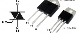
A simple homemade magnetically controlled contact (reed switch). How to make a reed switch yourself.
Home craftsmen have known the reed switch for several decades. This is a small glass bulb into which 2 or 3 contacts are soldered, at the ends of which there are small thickenings made of a special material. If a reed switch is placed in a strong magnetic field, its contacts become magnetized and attract each other. Although there are options when they are repelled, the so-called. normally closed contacts.
The vast majority of reed switches are a normally open pair of contacts. It is quite rare to see opening or switching ones. Another “mass” sign of reed switches is rather weak switched currents, tens of mA, sometimes hundreds. All this is a serious disadvantage of reed switches, which does not allow them to be used “directly” for switching powerful devices. Meanwhile, they could be applied anywhere. Instead of complex electronic devices, it would be enough to use a single but powerful switching reed switch, for example.
Fortunately, you can make a reed switch yourself. In general, this will not be a reed switch, like a “SEALET CONTACT”, but rather a magnetically controlled contact. But if desired, it can also be made airtight, so we will still call it a reed switch.
And in size it will be much smaller than a regular reed switch. But we are free to make it in any configuration, closing, breaking or switching. And more than one group of contacts.
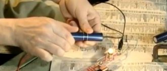
The design of a homemade “reed switch” is clear from the sketch. We will need at least one elastic plate, preferably made of a non-magnetic material. This can be a straightened copper or brass strip, a plate from the contacts of a large relay (this is the best option). The second plate can be inelastic and, in general, be a conductor on the board. (the sketch shows only the principle of operation). It’s good if there are so-called on the plate. points through which electrical contact actually occurs. They are sure to be on the relay plates.
On an elastic plate, using a drop of epoxy resin or cyanoacrylate glue (the one that glues everything in 5 seconds), we glue a small piece of iron of any shape. Now, as you might guess, if you move the magnet from the right side, the iron will begin to be attracted to it, the plate will bend and the contacts will close. That’s the whole “secret” of a homemade magnetically controlled contact.
To make a disconnecting reed switch, there are two options. The first is to use already closed contacts and bring the magnet on the other side. Then the iron, being attracted and bending the plate, will break the contact. If for some reason this cannot be done, then instead of iron you can glue a small magnet. And then, depending on the orientation (polarity) of the applied (control) magnet and depending on which side it is brought from, the plate will either open or, conversely, be pressed harder.
Of course, the disadvantage of such a primitive design is obvious. If an ordinary reed switch is triggered at any orientation of the control magnet, the very fact of the presence of a magnetic field is important, then our homemade one requires a more careful approach. But in fairness, this is not even a drawback, but rather a potential opportunity.
Imagine that an elastic plate is located between two others, but without a magnetic field it is not closed to anyone. There is a magnet attached to it. If we bring a control magnet with the same polarity, the plate will begin to attract or repel and close with one plate. And if we change the polarity of the control magnet, then contact will occur with the other. We got not just a switching reed switch, but a reed switch with 3 positions! This opens up very good prospects for controlling devices that require reversing, or “secret” control (electric locks, for example).
Since the dimensions of our homemade magnetically controlled one are quite large, the switched currents can be significant. In addition, these contacts have a certain “toggle” effect. Those. They do not switch smoothly, but rather abruptly, like a toggle switch. This reduces sparking at the spark plugs. The fact is that the elastic plate resists the creation of contact. And the dependence of the resistance force on bending is linear. And magnetic forces depend on the square of the distance between the magnets. Therefore, while the plate gradually increases resistance, the magnet, as the object of attraction approaches, pulls the stronger the closer the object is.
As you can see, there is nothing complicated about making a homemade magnetic contact, and anyone can make it in just a few minutes. Of course, it is best to use the strongest and most compact magnets. Although small in size, they have enormous magnetic force. But regular ferrite ones will also work.
You can use such contacts anywhere. In various automation systems, alarm systems, access control systems, sensors, etc.
Source
WATER LEVEL INDICATOR
| Good day, dear visitors and guests of the Radioscott website. It happens that you need to find out how much water is left in some opaque container. For example, a tank, barrel or any other, buried in the ground or raised to a height so that its contents are not visible. Then a water level sensor will come to the rescue. The circuit is so simple that even someone who has just picked up a soldering iron can repeat it. It consists of only 10 resistors, 3 transistors and 3 LEDs. |
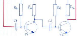
Liquid level indicator circuit
Let's start building the sensor circuit. First, we cut the board 30 mm by 45 mm. Then we will draw the paths, as in the photo. It is advisable to paint with paint or nail polish. But I only had a marker on hand (I would like to note that only a permanent marker will do). If you draw with a marker, then a marker purchased from a CD or computer store will hold up best. Once you've drawn, start etching.
I poisoned with hydrogen peroxide, since there is no ferric chloride or copper sulfate.
I poured 50 ml of 3% hydrogen peroxide, then added 1 tablespoon of salt and 2 tablespoons of citric acid. Mixed until everything was dissolved. With occasional gentle rocking, I etched the board in about 50 minutes. Let's start soldering the circuit. For this we need: 3 resistors with a resistance of 10 kOhm, 3 resistors with a resistance of 1 kOhm, 2 green and 1 red LEDs, 4 resistors of 300 Ohms. Having carefully soldered everything in, solder the wires and connect the battery. We cut the wires every 2 centimeters. Ready! Now we lower the wires into the glass and gradually pour water. For clarity, I slightly tinted the water. As you can see, everything works great. When the glass contains 1/3 of water, only the red LED lights up. When 2/3, the green light also lights up. And when the glass is filled to the top line, all the LEDs light up. in my case, I assembled a circuit with only 3 LEDs, but you can do more - at least 10. Then the water level will be visible more accurately. I would also like to add that the case was used under a corrector. Circuit assembled by: bkmz268 Forum on simple automation devices
Source
Tags: door switches
Comments 132
And I ordered these shitty limit switches from Aliexpress, and everything is as simple as shelling pears, I decided to make a display of the switched on speed on the mechanic, there is a place on the dashboard where I can implement all this, I was looking for a question about reed switches, I immediately came across your article, there will be more reed switches in the car
Hello! Photo: “We solder it to the connector going into the door.” What kind of connector is this?
Hello! The connector to which the microswitch is connected in the lock itself (which we are changing). We disconnect it from the mating part, the wires from which go into the door harness, and solder the reed switch to it.
This is understandable, but what is the connector that is highlighted in a circle?
I can't understand the question. This is the connector for connecting the door lock switch to the harness. It lies in the door so that you can remove the lock without cutting the wire (the limit switch itself is located in the lock and therefore the lock cannot be removed without disconnecting this connector). I have highlighted with a circle the part that is connected to the harness. The mating part remains on the wires of the lock (standard limit switch).
So I'm looking for this plastic connector that has a white and black wire going to it.
The fifth year of operation has begun: Nothing has been demagnetized or remagnetized. The reed switches are all intact, have not cracked or crumbled due to frequent door impacts, everything works as it did on the first day of installation. Not a single false alarm for the entire period. Let's move on!
On foreign cars (Alfa Romeo 164, 1991) a reed switch has been installed for a long time, right in the lock.
damn genius...everything is AWESOME! Definitely bookmarked... it’s not for nothing that they say “everything ingenious is simple”
Cheap and cheerful! Well done! And about the fact that there are special organizations that develop limit switches, aren’t they the ones who developed these same limit switches... and if you put a reed switch in glue or sealant, then it will live forever! There are all sorts of clever masters who will try to refute this... The forum exists for this purpose, to show what I did, I tested it, I liked it, I will continue to use it... then someone else either accepts his decision or not. Well done author!
Will magnetization of the metal around the magnet not occur over time?
if it happened, it happened immediately
Will magnetization of the metal around the magnet not occur over time?
During operation, the logic of operation has not changed; when closed with one click, it shows the door is not closed and the light does not go out. Near the magnet, the metal is slightly magnetized, but I think there is not enough force to influence the reed switch, especially since it is located perpendicular to the magnet, and when the magnet moves to the side by 2-3 mm, the reed switch turns on (during experiments before installation).
very useful, you should try it for yourself. definitely bookmarked, thanks
How did you bookmark it? The new look of the site is complete crap, so, like everywhere else, I guess the bookmark button (star) has disappeared?
I just copied the link and bookmarked it in my browser))
Great idea and excellent execution! Well done!
In Saabs, reed switches are standard. No problem.
brilliant definitely bookmarked
Why not put a reed switch in the rack and a magnet on the door, why would there be an extra wire in the door...
So we have a limit switch in the door (lock) and the standard wire is already laid there. If the limit switch is located on the counter, naturally there is no need to carry anything extra through the door.
Plusan about the clumsiness of the solution. You need to fill the inside well and fix the conclusions. Heat shrinkage is useless in this matter.
Well, the most important point is that over time, the metal around the reed switch will be magnetized. It is for this purpose that the diameter of the plastic case for use in metal doors is made larger (IO102-6).
In this case, heat shrink secures the soldered wires so that the reed switch, which is fixed in the piston with silicone sealant, does not pull; I missed this point in the description. I can’t say anything about magnetization; how do such devices work in computer hard drives, speaker systems, DC motors and the like, etc.
I repeat. The inside should not be poured from above, but poured inside completely. It is extremely difficult to do this at home - you either need a particularly fluid sealant or apply it under pressure. Where are the reed switches in hard drives?
There are organizations that are involved in development, testing and certification. And more than one certified engineer works there, in various fields. Do you consider yourself smarter than them? For God's sake, pick up the flag. Only literate people, in such cases of a hellish collective farm, clearly do not recommend repeating this to others. We must be responsible for our words. And do not confuse the result achieved now and long-term reliability, which is most important.
PS. I am especially pleased with such recent posts, which it turns out have been implemented for many years. What becomes clear during the discussion. ZZY. And I don’t need to tell you about the door switches. I had them repaired on the wagons, there it is a design problem. The insertion of external ones is an unjustified collective farm.
Yes, there are different organizations, they develop and test a lot of things... But why do such forums and communities exist? Have you ever thought about it? What kind of responsibility are we talking about? What words? Are you playing the role of a technical censor here? Judging by the fact that it is extremely difficult for you to force sealant into a tube, the level of technical thinking is clear. I heard your opinion and made my own conclusions.
Due to the narrowness of thinking, you cannot assume that someone puts reliability and repeatability above immediate success. Good luck with your collective farming. You even draw conclusions about the abilities of others based on yourself, which is significant.
Your well-reasoned comments reminded me of a dialogue from a well-known joke:
-God sent me Jesus!
from the next room
-doctor! I didn't send anyone!
There are organizations that are involved in development, testing and certification. And more than one certified engineer works there, in various fields. Do you consider yourself smarter than them? For God's sake, pick up the flag. Only literate people, in such cases of a hellish collective farm, clearly do not recommend repeating this to others. We must be responsible for our words. And do not confuse the result achieved now and long-term reliability, which is most important.
PS. I am especially pleased with such recent posts, which it turns out have been implemented for many years. What becomes clear during the discussion. ZZY. And I don’t need to tell you about the door switches. I had them repaired on the wagons, there it is a design problem. The insertion of external ones is an unjustified collective farm.
Repairing a standard Vagov's one is not at all difficult, half an hour of time, less than 100 rubles, the price of the issue, if it's a Soviet trailer or 500 for a Chinese one, it's even easier and faster. A bonus is the prevention of the castle, the elimination of a couple more birth defects.
so it’s a hassle to replace, and the author writes that he’s already changed it twice in a circle, which means there’s a problem)
This means that the technology has not been worked out. Out of several dozen repairs over five years, I had less than 5 returns.
One of the “harmful” pieces of advice: reed switches are not designed to work in vibration conditions. They have a weak point - the junction of the glass bulb at the point where the leads enter, and it cracks there.
About vibration is written at the end of the note. There is no load at the junction of the bulb and the leads, the leads are on one side, the reed switch together with the leads are in silicone sealant.
It doesn’t matter whether there is a load on the terminals or not, there is a weak point in the design of the reed switch - the junction point. leads and glass, your design is not damped from the machine body, therefore vibration is transmitted to the reed switch body and to the contact structure inside the body. They broke even when hard-soldered into the board. Then they would have used something solid.
Is there anything suitable solid-state, just without any Arduino, and just as simple and inexpensive?
Look at the Hall sensors, but you won’t be able to simply plug them in without a harness, you need power and most likely an output relay. The simplest and most reliable solution is high-quality fur. button. Or look here for inductive ones www.sensor-com.ru/catalog…yclid=4243717244201210049
DHs are quite capricious, industrial sensors are unreasonably expensive. The optics are good for everyone, but the doors will require maintenance.
Therefore, mechanics are better
Mechanics are different mechanics. It’s one thing to have a huge sealed oak end stop in the doorway, and quite another thing to have an unfortunate door stop in the lock, to replace which you have to dismantle half the door.
One of the “harmful” pieces of advice: reed switches are not designed to work in vibration conditions. They have a weak point - the junction of the glass bulb at the point where the leads enter, and it cracks there.
In cars, reed switches are used everywhere and do not break due to vibration. Transistors and microcircuits of the fifth acceptance are in metal-glass cases, and endure vibrations in machines that fly.
We were talking about simple glass reed switches without 5 reception and not in a metal-ceramic housing.
It's posts like these that make it worth coming here. Simple, elegant, versatile. Thank you.
Source
Advantages of TTP
The advantages of the relay include:
- the ability to switch relatively powerful loads;
- high performance;
- work in conditions of galvanic isolation;
- ability to withstand short-term overloads.
Not a single sample of mechanical or electromechanical products is able to compete with electronic switches. Therefore, new structures based on semiconductors have completely replaced the old mechanical samples.
The unique operational characteristics of TSRs allow them to be used without any restrictions while simultaneously increasing the operating life. All of the listed advantages of these devices are an excellent reason to try to assemble a solid-state relay with your own hands. The disadvantages of these products include the need for additional power, as well as the need to remove excess heat generated when working with heavy loads.
What is a reed switch
A reed switch is a type of relay. The word "reed switch" is an abbreviation for the words "sealed contact". This is the main feature of this electronic device.
Sealed contact
Conventional electromagnetic relays have movable and fixed metal contacts. There is an air gap between them. When they close or open, an electric arc is formed. The air between the contacts acts as a conductor. Arcing damages the contacts and shortens the life of the relay.
A reed switch works in a similar way, but the terminals are in an inert gas environment. For this reason, arc ignition is not possible. Consequently, the reed relay contacts do not burn out, which increases the service life of the electronic device.
The simplest DIY ANTI-THEFT (two schemes)
The proposed anti-theft scheme is suitable for protecting against theft of a car, motorcycle or moped. In cars with an installed security system, it can play the role of an additional means against intruders. Its main advantages are simplicity, low cost and reliability. To assemble a circuit with your own hands, you do not need expensive and complex components.
The article describes in simple words all the details, their purpose and operating principle, which will allow even those who have no idea what radio electronics are to understand the topic. In total, two variants of the circuit are offered.
Part device
The reed switch sensor looks like a small glass tube made of green translucent glass. There are wire leads on both sides. They allow you to solder the part to the board or connect wires to it. There are also three-pin models.
Inside the glass tube there is a cavity with an airless environment. The cavity contains contacts that are connected to the terminals of the device located outside. This part does not have semiconductors. Therefore, it can operate on alternating current.
Reed switches are quite varied in size. Small models have a length of 10-15 mm. The larger ones are the size of a palm.
This is interesting! There is a tendency to reduce the overall dimensions of reed switches. In 2022, the American company put into mass production a part with a tube length of 4.01 mm. In 2005, the Japanese also had achievements in this area and announced the production of a prototype with a flask length of 2 mm. However, these details have not yet received wide distribution.
Explanation of markings
On electrical circuit diagrams, the reed switch is designated as a circle with normally open or normally closed contacts. The symbol resembles an ordinary button surrounded by a circle.
In the technical documentation, the reed switch is marked with letters and numbers. For the designations of most such devices, the following is true:
- 1st character – name of the part (MK – magnetically controlled contact);
- 2nd symbol – type of contacts (A – normally open, B – normally closed)
- 3rd symbol – the letter “P” is indicated only on devices with mercury;
- 4th character – length of the flask in millimeters (two-digit number);
- 5th character – functional feature of the device (1 – low and medium power, 2 – high power);
- The 6th character is the serial number of the development.
Designation system for reed relays
For example, you can disassemble the MKA-14103 model:
- MK – magnetically controlled contact;
- A – closing;
- the letter “P” is missing, which means without mercury;
- 14 – flask length 14 mm.
- 1 – low or medium power;
- 03 – development order (useless in practice).
Operating principle of a reed switch
The contacts are activated under the influence of a magnetic field. Its source is usually a permanent or controlled electric magnet.
The field from the magnet easily penetrates through the glass into the sealed cavity. Once inside, it interacts with the metal contacts of the device.
The magnetic field sets them in motion, thereby closing or opening the electrical circuit connected to the terminals of the part. Therefore, to check the functionality of such a relay, it is enough to bring any magnet to it.
Operating principle of a reed sensor
Closing and opening contacts requires some magnetization time. It is measured in units of milliseconds, so in practice it is usually not taken into account. In most cases, it is acceptable to assume that the reed switch is triggered immediately when it enters a magnetic field.
Simple examples of everyday use
The reed switch is a simple part, so radio amateurs willingly assemble various devices on it with their own hands. Below are 3 popular solutions that are implemented using this part:
- Signaling. A secret magnet is attached to the door (it is advisable to use neodymium). A door reed switch is installed on the cladding. It is necessary to fasten it so that when the passage is open, the reed switch terminals are open, and when the passage is closed, they are closed. As a result, the door status is converted into an electrical signal. It can also be converted into an alarm sound.
- Homemade on-board computer for a bicycle. In this case, the magnet is installed on the wheel or drive sprocket of the bicycle. The reed switch is fixed on the frame of the “iron horse”. The higher the speed of the bicycle, the more often the magnet comes into close proximity to the part. Using a microcontroller circuit, these pulses can be converted into the current speed of the bicycle or the distance traveled per day can be calculated.
- Use as a limit switch on moving mechanisms (for example, on automatic gates).
Additional Information! The electronics industry also produces reed switches for security alarms. Such amateur-class devices include the wireless door opening sensor ALD01. Professional systems use mortise reed switches, which do not attract attention. They allow you to hide the fact that the detector is operating.
The operating principle of a reed switch is based on its interaction with a magnetic field. If you bring a magnetized object to the reed switch, its terminals will close. And if you place this part in the field of a controlled electric magnet, you will get a relay with increased wear resistance.
Technical parameters of choice
When choosing, you should take into account a number of technical characteristics of this device. The main ones include:
Additional Information! The contact resistance of contacts can increase as they wear out. It also depends on the strength of the magnetic field acting on the reed switch and its position in space.
Advantages and disadvantages
Like any electronic components, reed switches have advantages and disadvantages. Advantages:
- increased wear resistance;
- compact overall dimensions relative to conventional relays;
- absence of intrinsic noise and signal distortion;
- contacts are isolated from environmental dust.
- inability to work in conditions of extraneous magnetic fields;
- spontaneous opening and sticking of contacts at high currents;
- fragility, vibration intolerance;
- increased contact bounce due to their elasticity.
How to operate a reed switch
Reed switches close (open) contacts when exposed to a magnetic field. The field source is usually a permanent or electric magnet.
If we are talking about a permanent magnet, then the reed switch is in a closed state when the magnet is nearby. If you move it to the side by 5-7 mm, the contacts of the device will open.
With an electric magnet, you don't need to move anything. The reed switch tube is located inside the electromagnet coil. When voltage is applied to it, a magnetic field is generated. It keeps the terminals closed. If the voltage is removed from the electromagnet, the field will disappear and the terminals will open.
Electromagnetic switch with reed switch
Secondary direct acting overcurrent relays
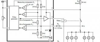
Of the current relays that industry produces, the simplest are direct-acting maximum current relays. Despite the different designs of these relays, all their operation is based on the electromagnetic principle. Relay coil 3 is connected in series with the secondary winding of the measuring current transformer 6. When operating current flows through supply line A (normal operating mode of the electrical receiver), electromagnetic core 4 will not be drawn into the coil, since the electromagnetic force Fe created by the relay winding will be significantly less, than the counteracting force of the spring Fп.
Current relay diagram.
If a short circuit occurs on line A, the relay coil current will increase significantly and become greater than the set value. In this case, the electromagnetic force of the coil Fe will exceed the counteracting force of the spring Fп, which will lead to the retraction of the core into the relay coil. After retracting the core into the coil, the moving system 2 will unlock the latch of switch B, which holds the switch in the on position. Under the action of the opening spring 1, the switch will break the circuit of line A.
It will be interesting➡ What is an intermediate relay?
The industry produces secondary overcurrent relays of the RTV type (time-delay current relay) and RTM (instantaneous current relay). The RTM has a rotary switch with which you can change the number of turns of the coil, which, in turn, will change the value of the operating current setting. The current setting is the setting of the relay for a given operating current. The standard provides the following settings: 5, 7, 9, 13 and 15 A. Relay operation current is the minimum value of the current flowing through the winding at which the relay is activated (Iср).
If it is necessary to disconnect a section of an electrical circuit with a time delay, an RTV is used, which, as a rule, has the same design, but is additionally equipped with a time delay mechanism (clock mechanism). This mechanism, attached to the core, keeps it from being instantly drawn into the coil, thereby changing its response time setting. The speed of the clock mechanism directly depends on the current flowing in the relay coil.
Setting the time is setting the time delay mechanism to a certain value in seconds. The relay has current settings of 5, 6, 7, 8, 9, 10 A. RTV and RTM are called built-in, since they are built directly into the switch drives. To directly trip the switch, these relays must develop enormous forces, which makes their designs bulky, which affects accuracy.
Interesting material to familiarize yourself with: what you need to know about the design of a power transformer.
Reed switch – from a children's toy to a protective system
Reed switch is a sealed contact controlled by a magnet. Important important parts:
- core made of soft magnetic material;
- insulator gaskets;
- contacts made of soft magnetic material;
- coil;
- hermetic shell.
Working principle: when electric current passes through the coil, it magnetizes the contacts, which close. To turn off the power to the contacts, it is enough to stop supplying current to the coil.
For the reed switch to work, you need to create a magnetic field
a certain tension value.
This value should be sufficient for the contacts to overcome elastic forces.
The devices have been used for about a hundred years due to their operational reliability and durability. Reed switches are produced in making, breaking and switching models.
Advantages of the switching device:
- strength that exceeds other similar partings by tens of times;
- performance, the value of which ranges from 0.2 to 2 ms;
- durability and large reserve. Manufacturers' warranty: up to 5 billion operations without reducing practical criteria;
- do not require additional power sources.
The main disadvantages of reed switches are the fragility of the cylinders and low switching power.
Design features of reed sensors
According to their design, reed switches are divided into:
- Open
- Closed
- Switching
- Open mercury
A very popular type of reed switch is the open reed switch. Each contact in a glass container is a flat wire. The contact surfaces are coated with gold, palladium, radium or silver, which helps reduce resistance and makes it possible to protect the contacts from corrosive processes.
The space of the glass flask is filled with hydrogen, argon or nitrogen, or simply represents a vacuum space, which also helps to increase the anti-corrosion parameters.
How to Choose Professional Technical Services for Reed Switch Connection
It will not be difficult to implement the connection of a reed switch with your own hands, having the abilities and knowledge in this area. If you lack the competence to connect the sensor with your own hands, then it is better to turn to the services of professional services that will carry out the connection cheaply and very quickly.
To select such services using the Yudu service, you need:
- Write a statement on the resource or call the indicated contact numbers
- Set the desired price for the service
- Find the offer that suits you best
- Get acquainted with reliable reviews about the work of performers
- Contact the selected service and arrange a visit
Types of TTP
When assembling solid-state relay circuits with your own hands, you should keep in mind that a variety of components can be used for these purposes.
Nothing prevents the person who takes up the job from choosing modern field-effect transistors, for example, characterized by high performance and low power consumption. These elements are controlled only by potentials, providing the ability to switch sufficiently powerful consumers. Field structures such as MOSFETs are capable of switching load circuits whose power reaches tens of kW. To independently manufacture a solid-state relay, it is possible to select other semiconductor structures capable of controlling power circuits: thyristors, for example, or bipolar transistors. The main thing is that they meet the requirements for the functionality of this circuit and the operating parameters of the elements included in its composition. Everything else depends on the preparedness and attentiveness of the performer.