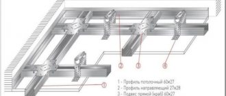
Every owner of private real estate, be it a house, apartment or cottage, will definitely be faced with the need to completely replace, partially repair or install “from scratch on a turnkey basis” the electrical wiring in his property. Naturally, in any of these situations, a person with an average income wants to save as much as possible, for which he is ready to do part or all of the work with his own hands. But you should know that without basic knowledge in the field of design and installation of electrical wiring, you should not take on such work. Electricians require a professional approach, otherwise you should forget about saving, because the stingy pays twice!
It is possible to carry out all the work on drawing up a wiring diagram and installing electrical wiring in an apartment, private house or country house with your own hands, but only if the owner is ready to understand this issue, study regulatory documents and strictly follow the instructions for carrying out the work. If you are not ready for this, then it is better to turn to specialists. This article is intended for those who are ready to create their own electrical wiring on their own. In it we will look at the first stage of work, namely: designing electrical wiring in a private house, apartment or country house! So let's get started!
Why do you need an internal wiring plan?
A detailed plan or wiring diagram is a complete drawing that shows all the elements of the internal power supply system of a residential or other facility: wiring or cables, distribution boxes, protective devices, control devices, switches, sockets and, if necessary, a ground loop. For each object, be it an apartment, a summer house or a private house, its own plan is developed if it is not built according to a standard design. But in any case, a wiring diagram is necessary. Its presence provides the following advantages when performing installation work.
- Having at your disposal a detailed electrical wiring plan, you can make a list in advance of the components, equipment and materials required to complete the installation of the electrical network. This will allow you to select and purchase products at the best prices without haste, which will ultimately lead to significant savings.
- A detailed plan will allow for the optimal distribution of network capacity. The drawing will clearly show where the nodes with the highest power consumption are located, which will allow you to plan the wiring in such a way as to eliminate the possibility of overheating of the wires due to excessive load. This approach will ensure high fire safety of the network as a whole.
In addition, the presence of a pre-developed diagram will allow you to clearly plan installation work and break it down into stages, which will prevent you from forgetting to install one or another element of the system.
Selecting a touch light switch
Before purchasing a device, you need to determine its functionality. To do this, the following criteria must be taken into account:
- Power of connected equipment and its connection diagram.
- Execution corresponding to the type of wiring.
- Operating conditions (if installation is planned in the bathroom, then a device with moisture protection is selected).
- Possibility of remote control (remote control or smartphone).
- Compliance of the design with the interior of the room, etc.
Having decided on the main tasks, you can begin to select a manufacturer. Naturally, you should give preference to well-known brands whose products are reliable. But at the same time, it is necessary to take into account the presence in the model range of switches of devices with the necessary functions. For example, Delumo has devices controlled by a radio remote control, and Sonoff specializes in Wi-Fi devices, Capsens Domuns Line lamps are “tailored” only for their touch switches, etc. There can be many nuances, so we recommend that you study the various options in detail.
Based on practical experience, in addition to well-known brands such as Legrand, we can recommend Vento Electric, Wemmon, Fanri, Merten, CGSS, Steu, Schneider, Ariston, etc.
MakeGood Classic wireless touch switch with remote control and backlight
We recommend monitoring online reviews where ratings of the best manufacturers are published. Selection criteria are made both by the model range of manufacturers, taking into account functionality and cost, and by other indicators.
Plan of the internal electrical network in a private house
Before drawing up a diagram indicating the location of cables and wires, it is necessary to draw up a detailed plan for the placement of household appliances, lighting devices and other electrical equipment both in the house itself and on the territory of the household. A schematic diagram of electrical wiring in a private house is developed based precisely on these data. For example, if in living rooms there are enough sockets for connecting low-power household appliances, then several separate lines must be installed in the kitchen and bathroom to provide electricity for powerful washing machines, microwave ovens, and so on.
Based on this plan, a schematic diagram of the electrical wiring is developed. It is considered the fundamental document for installation work and the purchase of all necessary components and materials. The diagram makes it possible to accurately calculate the length of the required cable and wires, their cross-section, the number of junction boxes, switches, sockets and other electrical wiring elements. It will not allow you to get confused when performing installation work and make mistakes in choosing components according to technical characteristics. A step-by-step plan for developing an electrical wiring diagram in a private house is given below.
- At the first stage, you need to decide on the type of electrical wiring. There are only two options: hidden or external. The first type is the most common. In this case, wires and cables are laid in special grooves cut into walls, floors or ceilings, after which they are walled up with cement mortar or other building materials. External wiring, very popular in the distant past, is now used in cases where it is not recommended to lay channels in the load-bearing structures of the house, namely in wooden buildings made of timber, rounded logs, and so on.
- Next, you should divide all electrical wiring into consumption groups. The entire network is divided into the following lines: for lighting, power outlets, power, street and for outbuildings. Each of the lines is drawn on a separate sheet indicating the dimensions of the rooms, the thickness of partitions and walls, and so on. In the final phase of this stage, according to the prepared data, a general plan for the electrical wiring of a private house with all network elements is drawn. The calculation of the required cable cross-section, the number of components and materials required for the installation of electrical wiring as a whole is carried out.
When developing a schematic diagram of electrical wiring in a private house, you should know that modern SNiP oblige the contractor to plan the wiring separately by room, with separate lines of sockets and lighting fixtures. This is due to the requirements for the safe operation of electrical networks. In addition, room-by-room division of internal wiring is more convenient to use. When carrying out repair work, there is no need to turn off the power to the entire house; it is enough to disconnect one room from the network.
Dividing the internal power supply network into lines according to power and consumption groups allows the use of electrical equipment and cable products with appropriate technical characteristics. For example, for a lighting line, you can use a wire with a cross-section of 1.5 mm² and a 16 A circuit breaker. This is enough for the normal functioning of several lamps. But to connect sockets, you need to use a cable with a cross-section of 25 mm², respectively, and a higher power circuit breaker of 25 A. All this allows you to optimize the technical characteristics of the entire internal network and reduce the cost of purchasing materials and equipment.
Important! The sum of the powers of electrical appliances connected to one line should not exceed 4.5 kW - this is the optimal indicator. For example, if household appliances with a total power of 4.2 kW are connected to one circuit in the kitchen, and you decide to install a boiler and an electric oven with a total power of 3 kW, then a separate line must be connected to this equipment.
All lines of wires and cables go to the electrical distribution panel. For each of them, an automatic circuit breaker of the appropriate power is installed and, if necessary, an RCD (residual current device). The electrical panel is an integral part of the entire internal wiring system and must be included in the electrical wiring diagram in a private house, apartment or country house. For a private home, it may be necessary to include a voltage stabilizer in the electrical wiring diagram, since the parameters of the electric current are very often unstable.
Attention! Voltage stabilizers will protect your household appliances from burnout and unstable operation. They are able to optimize the parameters of the electric current; the main thing is to correctly calculate the power of this device so that it is enough while simultaneously turning on all household electrical appliances and lighting.
Scope of application
Initially, this type of switch was planned to be used to turn on/off lighting, but the design turned out to be so successful that the scope of its application has expanded significantly. Today, most modern household appliances have touch controls; examples include kitchen stoves, hoods, microwaves, etc.
Kitchen hood Cata Midas 900
The only limitation on connecting to touch switches is the power of the equipment; its permissible parameters are indicated in the device passport.
Additional functionality
Modern technical base has made it possible to install microcontrollers in the electronic control unit of a touch switch, which has significantly expanded the functionality of switches and allowed them to fit into the concept of a smart home. Such switches can be controlled by voice, infrared or radio remote control, smartphone via WI-FI or a programmable timer.
The touch switch can be connected to the smart home system and controlled using a mobile phone
Touch switches can be used in conjunction with sensors that respond to motion or light levels. In the first case, such devices turn on a lamp, table lamp or other lighting fixtures when someone enters a room, such as a bathroom. With the second implementation option, the light will turn on at a low light level.
Sesoo triple touch switch and motion sensors
Some manufacturers, for example, Livolо, produce touch switches with a dimmer function or that control combined sockets, to which almost any household appliance can be connected.
Livolo touch switch with socket block
Electrical wiring design rules
It should be said right away that the set of rules, norms and requirements for the design of electrical wiring in a private house, apartment or country house is published in special documents and GOST standards. But in most cases there is no need to use such literature, especially when drawing up a wiring plan yourself. It is enough to comply with the most necessary standards, the list of which is presented below.
- All switches on the circuit diagram must be powered from the top line of wires, and the sockets from the bottom. Sockets must be located at least 30 cm from the floor level, and free access to them must be provided. Switches should be located at the entrance to the room, preferably in a place where it will not be blocked by an open door or other interior elements. According to the standards, sockets are prohibited from being installed in bathrooms and toilets, without including special current protective devices or step-down transformers in the electrical wiring diagram.
- All cables and wires in the circuit diagram must be routed in horizontal and vertical directions, and the angle of rotation of the lines must be straight at 90 degrees. Electrical wiring should not have any diagonal outlets, although such installation allows saving on materials, but according to the standards this is unacceptable. On the installation diagram, hidden wiring is shown in relation to the walls, floor and ceiling, that is, the distance from it to these structural elements of the house is indicated. A plan for the location of hidden wiring is necessary when carrying out various repair work.
- The cable or wires must be located at a certain distance from the structural elements of the house and communications. For example, for horizontal wiring lines, this distance to the ceiling should be more than 15 cm, from the floor more than 20 cm, and between the gas pipe and the cable it should be at least 40 cm. Vertical wiring lines should be located no closer than 10 cm from the corners, door and window openings. The distance between parallel-laid cables and wires must be at least 3 cm and they must be placed in protective boxes or corrugation, metal or plastic.
- It is not allowed to include the use of wires and cables made of different metals in the electrical wiring plan. If you cannot do without this, then it is necessary to connect conductors from different metals through a special coupling, otherwise they will quickly oxidize and fail. To connect lines or install a branch from them, on the electrical wiring diagram you need to indicate the locations of special branch boxes in which the conductors are connected on special mounting strips. It is not recommended to use twisting, as it is an unreliable connection.
Advantages of capacitive switches
Speaking about the advantages of this type of switches, the following qualities should be noted:
- Long service life. This is greatly facilitated by the absence of moving parts and contact groups.
- Compatible with all types of lighting fixtures. Models with dimming are available for LED strips and energy-saving lamps, if they have such an option. In addition, switching of any circuits that meet the operating conditions of the switches is allowed
- Availability of additional functions.
- Possibility of integration into the Smart Home system.
- Large selection of colors and designs.
Switches “Hares” model range Kopou - No mechanical contacts.
- The touch sensor can be installed in a standard “glass” for a hidden wiring switch.
Now briefly about the shortcomings. First of all, it is necessary to note the difference in cost with conventional mechanical switches, but it has become significantly less than 10-20 years ago. The price of inexpensive Chinese touchscreen models today is much cheaper than mechanical switches from well-known brands, such as GTS or Electronics.
Sometimes LED lamps connected to touch switches flicker. This may be due to both the low quality of the lighting sources themselves and the low-cost switch models. The problem can be resolved in two ways:
- Use products from well-known brands (Jazzway, Panasonic, Sapphire, Funry, LightaLight, Tronic, Sesso, etc.).
- Connect a 0.1 uF 630 V capacitor in parallel with the LED lamp.
Electrical wiring diagram in the apartment
Designing electrical wiring in an apartment is practically no different from the same work performed for a private house. The wiring diagram in the apartment is developed taking into account the same norms and rules. The only difference is that in most modern apartments an electrical panel is already installed on the site in the entrance. It is equipped with an electricity meter and the necessary modular devices: a primary circuit breaker and phase circuit breakers. Internal electrical wiring is also present, but in some cases it needs to be changed or installed from scratch.
In old multi-storey buildings, such work is carried out if the wiring does not meet modern requirements, and in new buildings, developers often sell apartments without an internal network, only with electricity supply to the electrical panel on the floor area. In all these cases, it is necessary to draw up a schematic diagram of the electrical wiring in the apartment for subsequent installation. At the top of the article, recommendations are given for developing a wiring plan in a private home. They are completely correct when carrying out such work in an apartment.
How to choose a cable
The main component of any electrical cable is the core through which the current passes. The cores are isolated from each other and placed in a common sheath. They can be solid single-wire or twisted from many thin wires, multi-wire. Single-wire ones differ little from multi-wire ones in terms of charge transfer speed; electricians look at other parameters: strength and flexibility. Novice installers choose multi-wire cables, which are a little more expensive, but they are more flexible, easier to work with and extremely difficult to damage, while a single-wire core in the hands of an inexperienced electrician will be cut short. Also: single-wire strands are fragile: bend them several times and they break. Single-wire cables are easier to strip and insert into the terminal, but now for stranded wires there are special connectors and lugs that collect and fix all the wires before connecting.
The veins are made of copper or aluminum. In premises, according to the current PUE, copper-based wiring is used, but in old houses aluminum wiring has been preserved.
TrionixFORUMHOUSE Member
It is cheaper to replace copper with aluminum now, not after a fire.
The most popular classification of electrical wires is by the number of cores.
Electrical wiring diagram in a country house
Designing electrical wiring in country houses is also subject to general rules. But since these real estate properties are not intended for permanent residence, the development of a schematic diagram of internal electrical wiring has its own nuances and they are as follows.
- Country houses are usually located outside the city limits. Power lines in such areas have their own characteristics. Basically, they were put into operation several decades ago and are not designed for modern load levels. As a result, power outages and sudden increases or decreases in network voltage occur. Negative consequences from the occurrence of such factors can be eliminated by including voltage stabilizers and reliable high-speed circuit breakers in the wiring diagram.
- Another feature of country houses that needs to be taken into account when developing an electrical wiring plan is the temporary residence of the owners. In most cases, dachas are used in the summer and closed for the winter. At this time, severe oxidation of wires and contacts occurs, which leads to failure of the electrical wiring. Therefore, in country houses it is recommended to design open electrical wiring, since it is easier to repair if malfunctions occur.
In all other respects, the electrical wiring project for a dacha is no different from the same scheme for an apartment or private house, only it is much simpler, due to the small size of the building and the small number of household appliances.
Design and operating principle
Despite the variety of models of touch communicators, most of them have a standard design consisting of the following elements:
- Housing made of heat-resistant plastic (see A in Fig. 1). The dimensions of the structure allow installation in a typical mounting location of a conventional switch.
- Electronic unit (B), it includes a power adapter and a semiconductor switch control circuit.
- Board with capacitive sensors (C).
- The front panel (D), as a rule, is made of quartz glass; budget models may use other materials.
Fig. 1. Legrand six-key touch wall switch
Now we’ll tell you how such devices work. The electronic unit monitors the state of the sensor. When you touch a certain place on the front panel of the switch with your hand (it is marked accordingly), the capacitance of the sensor changes. The electronic unit detects this and changes the state of the contactless semiconductor switch, which opens or closes the electrical circuit.
Briefly about security
When connecting touch control of lighting sources, you should adhere to the same rules and regulations as prescribed for mechanical switches. That is, before starting work, it is necessary to de-energize the line where the installation will be carried out. Further, we adhere to the following standards:
- The switches must be connected to the network in such a way that phase switching is carried out, not zero.
- If the power supply uses a ground wire, it must be connected to the appropriate terminal.
- If stranded wire is used for installation, its ends must be crimped or tinned. Otherwise, contact may be broken, which will lead to heating of the connection.
- Do not use a touch switch with obvious signs of a violation of the integrity of the structure.
- The load must match the parameters of the switch.
Lawnmower from a used motor
We continue to look for the answer to the question of where we can use the motor from an automatic washing machine. Another original idea is making a lawn mower. For a small area, an electric model connected to a power source with a cord is quite sufficient. The design of such a unit is very simple. You will need to make a platform on four wheels with a small diameter.
The platform can be made of metal or OSB board, plywood and even the body of the same washing machine
The engine is fixed on top of the platform, the shaft is threaded into the hole below, and the knife is attached to it. All that remains is to attach handles and a lever to the cart to turn the power on and off. If you have an asynchronous motor lying around, you will be surprised at how quiet the unit will be, even compared to factory models.
Advice! To prevent grass from wrapping around the knives, you need to slightly bend their cutting edges down.
Video: how to make a lawn mower
Theremin
The idea of a theremin was proposed in the era of the early “Middle Ages” of radio electronics - at the turn of the 20-30s of the 20th century by the inventor and musician Lev Theremin.
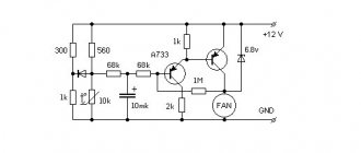
The operation of this electric musical instrument is based on the principle of comparing (subtracting) the frequencies of two generators.
One of the generators is a reference one, the second is controlled by approaching (removing) the palm of the hand. The closer the palm, the more noticeable the frequency shift of the second generator, the higher the sound at the output of the device.
Rice. 6. Scheme of a simple homemade theremin.
The model of the theremin, one of the very first electric musical instruments, can be assembled according to the diagram in Fig. 6. This device is a simplified modification of E. Aprelev’s circuit [M 6/92-28].
The signals from the two oscillators are subtracted in a special signal mixer. The difference frequency is fed to a sound emitter or low-frequency amplifier.
The initial operating frequency of the generators is close to 90 kHz. The antenna of the device is a copper or aluminum rod with a diameter of 2...4 mm and a length of 25...40 mm.
Of course, shown in Fig. 6, the sound generation diagram is noticeably simplified. In particular, for a “real” instrument it is necessary to adjust the volume of the instrument. For this, a similar second channel is usually used.
Shown in Fig. 6, the most simplified model of a theremin is built on the basis of two oscillators made on a microcircuit.
The initial generation frequency of both generators is the same and is set by capacitor SZ and potentiometer R1. The output signals from the generators through diodes VD1 and VD2 are fed to the input of the low-frequency amplifier (transistor VT1).
When your hand approaches the WA1 antenna, the operating frequency of the top generator in the circuit changes, which causes the appearance of a sound of changing tonality in the telephone capsule.
An original metal detector that responds to the appearance of a metal (conductive) object in the field of the device’s antenna can also be assembled according to the diagram in Fig. 6.
In combination with a conventional metal detector, this will allow you to more confidently recognize various objects (magnetic, diamagnetic, conductive and non-conductive) that fall within the field of action of the search coil or electrode.
Reflexology device
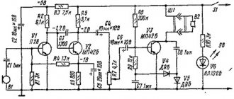
The diagram of the device - an electronic device for reflexology developed by I. Skulkin - is shown in Fig. 13 [Rl 2/97-26]. The search unit for biologically active points (BAP) contains an amplifier based on a composite transistor VT1 - VT3 and a pulse generator based on a DD1 microcircuit.
Rice. 13. Diagram of a reflexology device.
The search (active) electrode (A) is a rounded needle with a diameter of 1 mm. The passive electrode (P) consists of a section of a telescopic antenna.
When searching for BAP on the human body, this electrode is clamped in the hand. When the search electrode hits the BAP, the resistance of the skin area decreases sharply, and the device reacts to this by turning on the LED.
The polarity of the voltage applied to the biologically active point can be changed by switch SA1, and switch SA2 switches the device from the BAP search mode to the mode of influencing them. The frequency and current of the action are set by potentiometers R2 and R4, respectively.
To check the readiness of the device for operation, you should set the maximum exposure current in the “Search” mode (SA2) and close the electrodes. In this case, the HL1 LED should light up.
Oscillating gear reducer
2 - output shaft;
3 - toothed pulley hub;
4 - toothed pulley;
5 - meshed teeth of the swinging and driven gears.
One of the main parts of the gearbox is the swing gear. It is mounted on the hub of the drive pulley at an angle and therefore swings when rotating. It is kept from rotating relative to the gearbox housing by two leads sliding along the inner walls of the gearbox housing. During movement, only a pair of teeth on the oscillating gear are constantly in mesh with the teeth on the driven gear. Moreover, the swinging gear has one tooth more than the driven gear, so there is no full engagement. Only one tooth of the swinging gear with its side surface presses on the mating part of the driven gear, turning the latter at a small angle. As a result, for a full revolution of the toothed pulley, the driven gear moves only one tooth.
The driver can “tighten” the electromechanical parking brake even with the engine turned off, but release it only by turning on the ignition and pressing the brake pedal.
If the engine is running, the driver has closed the door and buckled up, the handbrake will turn off automatically when the accelerator is pressed. At the same time, the body roll sensor recognizes whether the car is on an incline, takes into account the position of the clutch and accelerator pedals and holds the brakes to prevent the car from rolling back.
Piston with screw pair:
Blown fuse indicator
L. Teslenko's fuse blown indicator (Fig. 10) contains a pulse generator on a microcircuit and an LED indicator [P 11/85-44].
Rice. 10. Fuse blown indicator diagram.
When the fuse is intact, a high level voltage is supplied to the inverter input (pin 8 of the DD1 chip), prohibiting the operation of the generator.
Once the fuse blows, pin 8 is connected to the common bus through the load resistance. The generator will start working, and the LED will blink at a frequency of about 5 Hz.
To indicate a blown fuse when the load is “broken,” it is advisable to include a resistor of about 1 MOhm in parallel with the load resistance.
Electronic traffic light model
The electronic traffic light model (Fig. 4) allows you to alternately switch multi-colored LEDs, simulating the operation of a real traffic light [Рл 10/98-15].
The timing circuit of the generator (R2, C2) determines the switching frequency of the green and red LEDs, and the circuit R1, C1 determines the glow time of the yellow LED. The duration of the green and red LEDs is about 10 seconds and is determined by the time constant R2C2, where the resistance is expressed in MOhms and the capacitance in μF.
Rice. 4. Electronic “traffic light” circuit.
What else can be made from a washing machine drum: original decor ideas
The drum with its correct perforation is a material for the manufacture of decorative objects. Here are some interesting ideas.
Ottoman with drum base. It’s easy to do – you just need to attach the wheeled legs and make a soft seat
Such a drum can also be turned into an original lamp. If you place a lamp inside, the perforated surface of the drum will cast glare on the walls. Such lamps will look good on the ceiling of the veranda or even on the floor
Bedside tables and tables. Drums with doors from top-loading machines can be used to hide small items.
This is how the drum turns into a cabinet or nightstand
We properly disassemble and decide what can be made from parts of an old washing machine
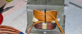
Disassembling a washing machine is a leisurely task. After working with water, a salt build-up may remain on the parts; it must be carefully removed so as not to damage the parts during removal. What can be made from an old washing machine? A motor will be useful for homemade projects - it will become the basis for many devices. The drum will also come into play. It is usually made of stainless steel. All pipes must be disconnected from the drum. A loading hatch may also be useful. In addition to these parts, do not rush to throw away springs, counterweights and body parts.
For those who are versed in electronics, you may need a circuit board - it can easily be used to find spare parts for repair work if necessary.
Color regulator
A simple color regulator can be assembled using a pulse generator with controlled duty cycle (Fig. 2). By changing the pause/pulse ratio using potentiometer R2, you can control the average current flowing through the LEDs HL1 and HL2.
Rice. 2. Color regulator diagram.
If these LEDs differ in glow color, by combining them under a common light-collecting screen, you can achieve a smooth change in the color of the total glow. You can turn on incandescent lamps as a load, thus obtaining a dimmer. To do this, you will have to use output stages with more powerful transistors.
Electric musical instrument
An electric musical instrument can be assembled on the DD1 K561LE5 microcircuit (Fig. 7) [Рл 9/97-28]. The pulse generator on three inverters of the DD1 microcircuit is controlled by keys S1 - Sn.
The rectangular pulse generator will operate at a frequency determined by resistors R1 - Rn (tens, hundreds of kOhms) connected to the common bus.
Rice. 7. Circuit diagram of an electric musical instrument on a microcircuit.
Keys S1 - Sn and key S2 must be closed at the same time (dependently). You should think about how to simplify switching by eliminating the SA2 key. The audio frequency signal through the amplifier stage (transistor VT1) is supplied to the telephone capsule BF1 or an external amplifier.
DIY touch switch
For those who like to work with a soldering iron, we can recommend several circuits of touch switches that will be easy to assemble with your own hands. Let's start with a simple field-effect transistor circuit, this is exactly the principle that was laid down in the first sensor devices.
Touch switch on a field-effect transistor
Designations:
- Resistances: R1 - 10..15 kOhm (must be selected for sensor response), R2 - 3...5 MOhm.
- Capacitors: C1 – 1000 pF (suppresses false triggering), C2 – 33.0 µF x 50 volts, C3 – 470 µF x 50 V.
- Transistor VT1 – KP 501A.
- Relay K1 can be used of any type whose operating current does not exceed 150.0 mA.
The circuit is powered from a source with a voltage of 12…24 V.
Now let's look at an option based on the NE555 asynchronous RS trigger. The device diagram is shown below.
Touch switch on NE555 chip
Designations:
- Resistors: R1 – 1.0 MOhm, R2 – 1.0 MOhm, R3 – 1.0 kOhm.
- Capacitors: C1 and C2 – 15 nF, C3 – 10 nF, C4 – 0.1 µF, C5 – 100.0 µF x 25 V.
- Diodes: D1-D2 – 1N4001, D3 – standard indicator LED.
- Microcircuit - NE555,
- The relay is the same as in the previous electrical circuit.
The above diagram does not need to be configured.
Concluding the topic of homemade sensor devices, we should mention the Ardunio system. On this platform, you can assemble a switching device that can be easily integrated into a Smart Home. In addition, such a device can be easily configured to operate independently, in accordance with a given program.
Compact touch sensor for the Ardunio system
In addition, the system allows you to create several profiles for specific tasks. However, this will require programming skills. You can get more detailed information about the Ardunio platform on our website.
Note that in the above circuits, a power source with a voltage of 12-24 V is required to power the control circuit. For this purpose, it is best to use switching power supplies. The electronic balance of LED and energy-saving lamps is ideal as such. Detailed information on this topic can also be found on our website.
Wheel parking brake mechanism
3 - drive belt;
4 - gearbox with a swinging washer.
The electric motor is connected through a toothed belt drive to a gearbox, which reduces the rotation speed of the output shaft by tens of times and makes it possible to develop the force necessary for the operation of the braking mechanisms.
If the car is stationary or moving slower than 7–10 km/h, the electric motors turn on, activating the brakes. At higher speeds, the ABS unit turns on the hydraulic pump - the pressure in the brake circuits increases. The car slows down and then puts the handbrake on.
Oscillating gear reducer: