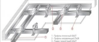
Drywall is a popular building material, which is used for the manufacture of interior partitions, as well as for covering ceiling surfaces and walls.
But it has one significant drawback - its heavy weight (one sheet, depending on the size and thickness, can weigh about 20-30 kg).
Therefore, as, for example, with slate, during installation work you will need at least 1-2 helpers.
Attaching gypsum boards to the ceiling surface yourself is very difficult and inconvenient, since you have to hold the sheet at a height and tighten the screws. Not to mention the fact that it still needs to be set correctly.
What consequences can there be if you lift a sheet of drywall alone without assistance?
Firstly, you can easily get injured at work (only at home). Secondly, you can break the sheet, and this is an additional financial expense.
But all these troubles can be avoided if you use a special mechanical device - a lift.
This is a very useful device that comes in handy when working with drywall of any size.
If you need to sheathe the ceiling, you can make a drywall lift with your own hands
.
We explain why the device is useful and how it helps in your work.
Holding a sheet of drywall aloft with your hands requires enormous physical effort. Whereas with the help of a lift, installation work is carried out much simpler, easier and faster.
The material is placed on the working platform of the lift, then, using a lifting mechanism (for example, a manual winch), it is raised to the required height - usually no more than 3 meters, and already at the top under the ceiling it can be positioned as you need. Details
We will talk about this device below.
Machine structure
The operating principle of a crane is based on the physics of simple mechanisms. The simplest version of the crane is a stick placed on a fulcrum in such a way that the free ends have different lengths. Now if you hang a load on a short lever, it will take less effort to lift it. The most common design is one that uses, in addition to levers, a system of blocks.
A do-it-yourself crane is an indisputable assistant in small-scale construction. When constructing a private house, the use of bulky industrial cranes is not required. The height of the houses rarely exceeds 2 floors, and the weight of the lifted load is 200 kilograms.
Crane diagram
Although there are many variations of lifting mechanisms, a classic crane consists of the following parts:
- An arrow with a block attached to its end. Depending on its length, the height to which the load can be lifted is determined.
- Platform. The boom and counterweight are attached to it. It is the main part of the crane and is subject to significant loads. Therefore, when manufacturing a platform, it is important to pay special attention to its strength.
- Counterweight. Serves for crane stability. Defines the maximum load weight that the crane can lift. Stackable counterweight options are available to provide maximum stability.
- A guy wire connecting the boom and the counterweight. Allows you to adjust the tilt of the boom and move the load in both vertical and horizontal planes.
- Winch with cable. It is the lifting mechanism itself. The power of the winch determines how much weight the crane can lift.
- Stand with a rotating mechanism. It is necessary to turn the crane to the sides.
- The support cross, which is the base of the crane. Sets the stability of the entire structure. When manufacturing it, you should also pay attention to its strength.
Principle of operation
During unloading, the driver must move the crane equipment to a position in which the oil fluid will flow in only one direction. After this, the power to the drive of the pumping mechanism is turned on, which takes part of the oil and transfers it under pressure to the body of the hydraulic cylinder.
When the body part is fully raised, the power to the hydraulic pump drive is turned off. The body will not be lowered thanks to the crane.
In order for the body to lower, the crane must be turned. After this, the oil fluid will begin to flow in the opposite direction, the pressure level in the hydraulic cylinder will begin to drop, and the loading platform, under the pressure of its own weight, will return to its original position.
terms of Use
To operate lifting mechanisms safely, certain rules must be followed.
Homemade Pioneer crane
These rules apply to any lifting device:
- The load capacity must not be exceeded. A load that is too heavy may damage the device.
- The base must be stable. Homemade lifting devices should be located on a previously prepared hard horizontal surface.
- In bad weather conditions, you should also refrain from working with the crane. Strong winds will throw the crane off balance, and poor visibility may make it difficult to see people under the boom.
- Before operating a crane or lifting device, it is necessary to conduct an external inspection to identify any malfunctions. If malfunctions are detected, operation of the crane is prohibited.
- It should be remembered that when working with the lift, you should not make sudden movements. The load must be lifted smoothly. And most importantly, do not stand under any lifted load.
Your own “lift”. Portal user elevators
In the first part of the article, we talked about the difficulties that await those who are thinking about having their own elevator in the house. Of course, for true “do-it-yourselfers” who are firmly confident in their own engineering abilities, they only inspire (to try) and provoke (to discuss). Especially those who have already made a similar elevator at home. And as their experience shows, an attentive mechanic and owner always have time for regular technical inspection and installation of numerous “protective” devices.
User Tehnoman identifies the following components of a “home” elevator:
1. Pit equipment: speed limiter tensioner. 2. Drive (winch). 3. Cabin:
- cabin frame;
- top beam;
- lower beam;
- riser;
- catcher;
- compartment cabin;
- floor (movable or fixed);
- cab door drive.
4. Counterweight. 5. Installation of guides. 6. Mine door. 7. Speed limiter.
Judging by the stories of portal participants, they adhere to exactly this layout (with minor variations).
. Several years ago, the user Grandfather completed renovations in an old village house. After all the alterations, he ended up with a spacious living room downstairs and a bedroom in the attic. All that remained was to make the stairs to the attic. However, after studying all the options, the craftsman abandoned this idea: the staircase would take up too much space, reducing the area of the room. As a result, he decided to make a device that, according to its characteristics, is classified as an elevator, since “an elevator is a more complex structure.”
However, it performs its functions properly. “I’ve been using the lift for three years, I’m very pleased,” Dedush wrote in 2014.
The design of the device is simple, he claims. The main parts of the lift are a cabin, guides with rollers, an electric hoist and control buttons with limiters. Cabin dimensions: 600*600 mm (length-width), height – 1800 mm. The side and rear walls of the cabin have continuous fencing; the top and entrance are left without fencing. The frame is made of a 45*45 mm bar. An electric hoist with a lifting capacity of 300 kg is located behind the attic wall on the ceiling. The support rope runs along the wall.
According to the user, the hardest thing for him was choosing the guides and rollers for the cabin. As a result, the search led to guides and rollers for hanging doors weighing up to 100 kg. The rollers are installed in 2 pieces at the top and bottom of the cabin - the top pair works to separate the guides, the bottom pair works to compress.
The cabin of such an elevator is designed for one person weighing up to 130 kg. To control the lift, three double (up and down), self-returning buttons are used: as long as you hold the button, the lift goes up or down. When you let go, it stops. The entire control system is switched to 12 volts. At the top and bottom, the circuit includes limit switches that provide stopping in the extreme positions of the cabin. Movement speed is 15 cm per second.
What characteristics should a garage lift have?
In garage conditions, two types of lifting mechanisms are used. The first type includes a lift that can lift the entire car, and the second type includes a goose-type lift that allows you to move loads around the garage.
Lifts of the first type are stationary devices and the main requirement for them is stability. The car weighs more than a ton and should not have the slightest chance of falling. In order to prevent any accidents, the garage lift must have a reliable stopper.
Homemade goose tap
The goose type lifts are most often used in auto repair shops. It is quite simple to make it from a profile pipe or channel. First, the base is welded on which the rotating mechanism needs to be installed. It is best to make an arrow with an adjustable reach. This will make it possible to move weights in any direction.
Dump truck installation for UAZ
Gazelle dump truck
Conversion into a dump truck
The dump truck is fully equipped; you don’t need to purchase anything additional. For installation you will need a grinder and a welding machine.
We send dump trucks to other regions of the TC.
| Wheelbase | 2550 mm |
| Curb weight | 1845 kg |
| Maximum weight of transported cargo | 1225 kg |
| Total transport weight | 3070 kg |
| Ground clearance distance | 205 mm |
| Maximum ford depth | 500 mm |
| Permissible towbar weight | 850 kg |
| Fuel tank volume | 56 l |
| Power unit power | 90 l. With. |
| Engine displacement | 2.44 l |
| Diameter of cylindrical parts | 92 mm |
| Piston stroke | 92 mm |
| Compression ratio | 6,7 |
| Rated torque | 415 Nm |
| On-board voltage | 12 V |
| Track | On the front wheels - 1500 mm On the rear wheels - 1442 mm |
| Average gasoline consumption per 100 km | 12 l |
| Maximum engine speed | 2100 rpm |
| Tire size | 8,40-15 |
| Maximum tire pressure of front and rear wheels | 2.2 kgf/cm³ |
| Steering wheel play | 100 mm |
| Operating temperature | -40…+40°С |
| Brake drum diameter | 280 mm |
| Braking distance from a speed of 60 km/h | 5500 mm |
| Pad width | 50 mm |
| External turning radius | 4700 mm |
| car model | Load capacity | Rear unloading | Unloading on three sides |
| UAZ3303, KIA, BONGO, PICKUP, FARMER | up to 2 tons | RUB 87,300 | RUB 97,300 |
| GAZ3302 GAZelle, any foreign-made trucks | up to 3 tons | RUB 95,300 | RUB 105,300 |
| GAZ310, VALDAI any foreign-made trucks | up to 4 tons | RUB 145,200 | RUB 155,100 |
| Assistance in re-registration with the traffic police: | individually |
| Installation of a dump truck in Novosibirsk | |
| Load capacity up to 3 tons: | 20,000 rub. |
| Load capacity over 3 tons: | 30,000 rub. |
| Accessories | |
| Hydraulic cylinder made in China (rear unloading) | 15,000 rub. |
| Hydroelectric station made in China | 25,000 rub. |
Our company is engaged in the conversion of onboard vehicles of domestic and imported production with a carrying capacity of up to 4 tons into dump trucks.
Unfortunately, the domestic industry does not offer a large selection of light-duty dump trucks, and the price of imported vehicles is very high. The demand for the services of dump trucks of such carrying capacity is growing every year. This is due, first of all, to the development of low-rise construction in Russia, when many people go to live outside the city, and low-tonnage dump trucks are in demand for delivering coal, firewood, humus and other materials.
We offer to professionally and completely legally convert your flatbed vehicle into a dump truck. Work completion time : 7 days
– Low cost of conversion – Registration with the State Traffic Safety Inspectorate – Entering a market where there is no competition – Increasing your income – Increasing the value and liquidity of your car
How a simple block design works
The pulley system or pulley system has been known to mankind since ancient times. The classic system design consists of pulleys and cable. One pulley is called a block. Depending on the method of fastening, the pulley can be movable or fixed:
- Fixed block. It is attached to the support and plays the role of changing the direction of movement of the rope. Does not provide any gain in strength.
- Movable block. It is located on the side of the load and gives a gain in strength.
The principle of operation of a pulley block is similar to the principle of operation of a lever in the physics of simple mechanisms. The role of the lever in this case is played by the cable itself. In the case of a simple block of two pulleys, the movable pulley divides the rope into 2 parts and in order to lift the load the same distance, a rope twice as long will be required. The work of lifting the load is performed in the same volume. And the effort, due to the fact that the length of the rope has become twice as long, becomes half as much.
If there are more than 2 pulleys in the system, the gain in strength is approximately equal to the number of blocks. In the case of 3 blocks, the effort will be 3 times less, and 4 blocks will require only a quarter of the original effort.
Dump truck installation for UAZ
UAZ-330365 (“Tadpole”) converted into a dump truck. UAZ-330365 Dump truck
The standard onboard platform and fastening elements were dismantled. A subframe with a dump body (two-way unloading) with hydraulic lifting equipment is installed on the chassis side members using standard fasteners. The subframe is secured to the car frame using stepladders.
The hydraulic distributor, power take-off box with hydraulic pump were installed in the place provided by the manufacturer, and the oil tank. Rear lights, battery, fuel tank, tail lights are installed and connected.
The vehicle complies with the requirements of clause 1.7 of Appendix No. 6 of TR CU 018/2011.
The maximum weight and its distribution along the axles and sides, as well as changes in the coordinates of the center of mass, do not exceed the limits established by the vehicle manufacturer.
The overall width does not exceed 2.55 m, and the height is 4.0 m.
The components and assemblies are securely fastened to the places provided by the design with elements similar in design, quantity and material to the fastening elements of the base car. Connections in the exhaust system, engine fuel supply, brake system, power steering system and power take-off with hydraulic pump are made using standard parts and structural elements (fittings, pipelines, hoses, etc.).
The dump body is securely fastened to the vehicle frame with fastening elements similar in design, quantity and material to the fastening elements of the body of the same vehicle, manufactured under mass production conditions, of the same or greater technically permissible maximum weight.
All wires are reliably protected and firmly attached to eliminate the possibility of breakage, chafing or wear. Every electrical circuit that powers any piece of equipment has a fuse or switch.
The driver's cabin is equipped with standard rear-view mirrors on both sides.
The vehicle complies with the requirements of clause 9 of Appendix 3 of TR CU 018/2011 regarding protection against splashing from under the wheels.
The location and installation of rear external lighting devices and rear state registration plate lighting devices comply with UNECE Regulation No. 48.
UAZ-330365 Dump body UAZ-330365 Dump body - tank for hydraulic fluid UAZ-330365 Hydraulic cylinder for driving the dump body UAZ-330365 Dump body in technological mode
Complex block system how to calculate power gain
If the system is designed in such a way that one simple pulley pulls another simple pulley, then this is already a complex system of blocks. To theoretically calculate the gain in strength, it is necessary to conditionally divide a complex chain hoist into simple ones and multiply the values of the gain from simple chain hoists.
For example, if the system consists of 4 blocks, and the first conditional simple pulley has a gain of 3. It pulls the second simple two-block pulley, also with a gain of 3. The total force that will need to be applied will be 9 times less. It is the 4-block complex chain hoist that is most often used by rescuers.
Lift-tilter
To avoid costs and a lot of complications, you can give preference to a simple garage lift-tipper. The device will allow you to tilt the car to one side, and the tilt angle can vary from 45° to 60°. This is quite enough for most repair work.
To build such a unit, you will have to create and connect a number of parts: the front pillar, beams (top, bottom, rear), shoe. Various connecting elements will also be required. You will need to work a lot with metal, so you must have a special tool - welding, a grinder and a drill with a set of metal drills. The main material for work is 4 mm steel sheets, angles and bushings.
Creating a Top Beam
Next, proceed directly to creating the top beam. For this, take two 1.5 m corners and weld them into a U-shaped profile. It is also necessary to weld a metal insert in the middle, which will ensure the fixation of the jack. The beam will be ready when you weld a plate of the appropriate length and height to the profile. The result is a rectangular beam. One end of it must be welded tightly - the bushing will be attached to it, and the guides for the jack are welded to the other end.
The platform for the beam is created from a steel sheet. You can bend its sides to get something like a box, or weld the walls of this very structure. Inside the site there will be a piece of wood of the required size, which is fixed with fasteners, and rubber is mounted on top of the wood. The platform is attached to the beam using a pre-welded eye.
Final stage
To ensure that the machine is securely supported on the opposite side of the lift, a rear beam is required. It is welded from 4 corners 32, 1500 mm long, so that in the end you get a square the length of a car. The beams are connected to each other through a special unit on the rear beam. The lower beam is also created from the corners and is connected to the rack and the rear beam. All that's left to do is to make the stud pins and install the jack. As a result, you will have an effective tipper.
Methods for attaching a rope to a lifting mechanism
When creating complex pulley blocks, there are often situations when a cable of the required length for attaching the moving block is not at hand.
Crane for gas blocks
Methods for attaching a cable using general-purpose rigging:
- Using a cord. Using a self-tightening knot, the cord is tied to the main cable. As the load is lifted, the grappling knot moves along the main rope, thereby allowing the height of the load to be increased.
- Using clamps. In the case of using a steel cable, it is not possible to use a cord, so it is necessary to use special clamps.
Comments
Hmm, well, making a homemade elevator is definitely not for a beginner. I would like to, of course, but I feel that my own knowledge is not enough. Maybe someone who is inexperienced like me has already tried to do this and share their experience?
Hmm, well, making a homemade elevator is definitely not for a beginner. I would like to, of course, but I feel that my own knowledge is not enough. Maybe someone who is inexperienced like me has already tried to do this and share their experience?
Alexey, an elevator in the basement is a very convenient thing, a friend of mine had it done by professionals, but if you really want to, I’m thinking of doing it yourself, but everything needs to be planned out very carefully, everything needs to be taken into account down to the smallest detail. Then everything will work out!
Alexey, an elevator in the basement is a very convenient thing, a friend of mine had it done by professionals, but if you really want to, I’m thinking of doing it yourself, but everything needs to be planned out very carefully, everything needs to be taken into account down to the smallest detail. Then everything will work out!
The elevator to the basement is convenient. Otherwise, in our basement you have to climb an ordinary wooden ladder and are constantly afraid that the crossbar under you will break off. Valery Ivanovich, where did your friend find these professionals? Who makes elevators like this anyway? Tell.
The elevator to the basement is convenient. Otherwise, in our basement you have to climb an ordinary wooden ladder and are constantly afraid that the crossbar under you will break off. Valery Ivanovich, where did your friend find these professionals? Who makes elevators like this anyway? Tell.
This is definitely a good idea. But here you either have to be a jack of all trades to build this on your own, or have a good friend to do this. What about companies that do similar things. Does anyone know these?
This is definitely a good idea. But here you either have to be a jack of all trades to build this on your own, or have a good friend to do this. What about companies that do similar things. Does anyone know these?
We create a simple lifting mechanism with our own hands
Construction of a crane is not a quick task and is justified if it is required frequently or the volume of work is large enough. In cases where the load needs to be lifted urgently or this is a one-time operation, you can use improvised means.
To create a simple lifting device you will need a cord and two blocks. One block and the end of the rope are fixed motionless on the support. This will be the highest point to which the load can be lifted. We attach the second block to the load using slings or a hook. We first pull the rope along the block attached to the load, then pass it through the upper block. The gain in power will be 2 times. Using your own weight, you can easily lift a load weighing 100 kilograms to the required height.
DIY mini crane
If you add the ability to move the upper block along a guide, for example along a rail, you can get a do-it-yourself jib crane. It is useful in garage conditions for moving heavy machine parts.
It should be remembered that when working with the lift, you should not make sudden movements. The load must be lifted smoothly. And most importantly, do not stand under any lifted load. The same rule applies to a crane - standing under the arrow is prohibited.
FakeHeader
Comments 39
oh, this will come in handy now, thanks)
I respect people with hands! yyyy
Yes, this is not for you to make a rake out of chairs on the press.
yyyy not rakes but daisies yy
Handsome. I liked it very much...the principle of the lift...must remember))
Well done! Cool idea and done!
cool and cool thing. It’s really possible without... yesterday I threw it like that.
You can also turn it with a screwdriver))
Wonderful device! I would “twist it” with a wrench or a low-speed drill, with reverse...
I will definitely make one for myself! It’s just convenient, and most importantly, it’s a very necessary device,
Great! But I don’t trust studs from a hardware store) a screw from a jack is better.
When lifting the box, the load on these studs is negligible. Let the screw from the jack be left for something more serious.
Wonderful and affordable! Question about the engine mount, which is visible in the photo... Is it made of a screw pair of vices (jack)? Or another principle?
The engine support is an old Soviet screw jack. I lift the Volga under the front beam for them, if it is necessary to lift the entire front.
I see... I have Gazelevsky for this.
Well done. 5+ But it’s not always convenient to turn this bolt. I have the same principle, only I bought it ready-made in Sorokina. and it would be even wider.
I turned the ratchet. Take your time - when I repair my cars, I’m not in a hurry, the main thing is that it’s done carefully. And the width is enough, at least for my purposes.
It is convenient to install the Volgov gearbox using an alternator belt. We put the belt on the gearbox and through the hole for the gearshift handle, pull the belt out of the passenger compartment, thread the mounting and tighten as required, fix it by resting the edge of the mounting on the seat. After this, from below we can turn the gearbox in all directions and move it back and forth left and right about 10 centimeters at a time, without holding it suspended.
What's the point of this comment?
Advice for those who will install a gearbox without a lift. And of course the device rules
It is convenient to install the Volgov gearbox using an alternator belt. We put the belt on the gearbox and through the hole for the gearshift handle, pull the belt out of the passenger compartment, thread the mounting and tighten as required, fix it by resting the edge of the mounting on the seat. After this, from below we can turn the gearbox in all directions and move it back and forth left and right about 10 centimeters at a time, without holding it suspended.
will it work with the classics? one of these days I'm going to take off the box and install it
A necessary device! How inconvenient it is to install and dismantle this gearbox and more, especially for one pair of hands!
Yes, the Zhiguli gearbox is inconvenient, the Volgov 5-mortar is heavy. It’s impossible to do it alone by hand without a curse word)
No auto repair shop is complete without a car lift. The equipment is available on the market in a wide variety of models from local and foreign manufacturers. A car lift installed in a car service will pay for itself quickly, but purchasing a car lift for personal needs is a stupid expense. Moreover, it is possible to build a car lift with your own hands.
Materials and tools
The most important thing when making a crane is to use high-quality tools and materials. This will guarantee that the structure will be strong and safe.
The cable should have minimal stretch; this will give a greater gain in strength when using a pulley system. The fittings used for tying must be taken only from metal. Plastic fittings cannot withstand heavy loads and break at the wrong time. To fasten individual parts of a homemade crane, you should choose high-strength hardware products.
If a winch is intended to be used, its lifting capacity should not be less than 500 kilograms. The best choice would be winches that can lift a load weighing 1 ton or more.
In conclusion, I would like to once again remind you of the need to observe safety precautions when working with lifting mechanisms. Also, regardless of whether the crane is purchased or made by yourself, you should inspect it before starting work.
Making a cellar elevator - step-by-step instructions
Before starting installation, you need to study the requirements of building codes, fire and electrical safety measures. First of all, design documentation is drawn up, estimates and calculations of materials are made.
The lift to the basement is made in the following sequence:
- Applying markings to the floor, walls and ceiling. Checking the vertical and horizontal lines, compliance of the holes with the diagrams.
- Manufacturing a frame for the movement of an elevator car. For this purpose, a steel angle is used, which is attached to the walls, ceiling and subfloor foundation, and the floor slab of the building.
- Cabin assembly. Equipping the product with rollers for movement along the guide frame. Installation of door and security railings.
- Fastening to the frame of the load-bearing beam. Attach the winch, motor, gearbox and coupling to it. Installation of cable and band brake.
- Connection of the cabin with the power plant. Checking the assembly quality, eliminating slack and play.
- Cleaning the structure from scale and dirt. Treatment of metal with anti-corrosion agents. Application of a protective coating.
- Installation of electrical wiring. It is better to carry it out in a corrugated metal tube rigidly fixed to the wall. Installation of switches on the top and bottom of the frame.
- Testing the mechanism in different modes, including during a sudden power outage.
After completing the assembly work, the elevator to the cellar is lowered to the lower position to relieve the supporting structures from constant pressure.