Starting the study of radio engineering for beginners
Before studying radio engineering or electronics, you need to understand why a person needs it. If this is a hobby for a couple of days or months, then it is better to quit the idea right away, because if you treat electronics carelessly and do not follow safety precautions, you can cause severe harm to your body. If you have been fascinated by this field since childhood, but did not have time to start studying, then now is the time to start. Gradual immersion implies:
- Obtaining or consolidating theoretical knowledge of physics. To begin with, it will be enough to have school knowledge of electrophysics, including a detailed study of Ohm's law - the basis of all electrics.
- Introduction to the theory. We should move from the more abstract things of physics to the more tangible. Theory implies an accurate and complete description of all concepts, parts, tools and devices that will be used in practice. It’s impossible to sit down and start soldering something without a theoretical foundation.
- Application in practice. The logical conclusion of the theory, which allows you to consolidate all the studied material and apply it when creating specific circuits or devices.
Types of electrical circuits
In practice, several types of electrical circuits are used:
- simple;
- installation;
- single-line;
- multi-line.
The first type is the most common. The main components and the order of their connection to each other are indicated on simple diagrams (DS). In addition, they are used to check the correct assembly. Wiring diagrams (MC) show the location of parts on the board or inside the case. Multilinear diagrams are used to depict three-phase circuits.
What is a datasheet and why is it needed?
Datasheet is a technical specification that provides complete information about a radio component. All technical information, basic connection diagram, parameters and types of housings are indicated in this document.
Datasheets come in different languages, mostly in English. There are also translated versions.
Documentation for the NE555 chip. The body and appearance of the part are drawn.
The microcircuit, its parameters and operating conditions are described in detail here.
Such documentation is available for any detail. This is very convenient and informative, especially when searching for analogues. And with the help of the Internet, searching for analogue parts or diagrams has become even easier.
The datasheet also allows you to identify an unknown part or microcircuit. Just write its name in a search engine, add the word datasheet, and all the documentation will be in the search results.
Basics of radio electronics
First, let's look at an ordinary AA battery. You can read on it that its voltage is 1.5 V. Let's check.
To do this, you will need a multimeter, that is, a digital measuring device. First, you should get a cheaper model, always with manual selection of the measurement range.
Voltage measurement
- connect the black wire to the “COM” connector;
- connect the red wire to the voltage measurement connector “V” (Connecting wires in another way may damage the meter);
- set the knob to the desired division - since we expect to get a value of approximately 1.5 V, then set the knob to a value of 20 in the DCV or V range (the straight line at the letter V means constant voltage);
- The metal tips of the multimeter wires touch the battery poles, but which end goes to which? Try both combinations - the result should be the same, only once it is shown as a "positive" number, in other cases it is preceded by a minus number. This doesn’t matter to us; nothing will happen to the voltmeter either;
- we read the value - in this case, the voltage of the new battery is 1.62 V;
- turn off the multimeter (don’t forget, otherwise the battery will run out).
Measuring the voltage of a 1.5 V battery: a) the red tip of the meter touches the plus of the battery - a positive result; b) the red tip of the meter touches the minus of the battery - a negative result with a minus in front of the numbers.
Attention! When carrying out measurements, in order not to damage the device, we always set the measurement range to a value exceeding the maximum result that we expect to obtain! If we don’t know what to expect, then the safest option is to set the meter to the highest possible range and then reduce it to the most accurate measurement.
Let's check other batteries/accumulators. For the tests we chose: a charged 1.2 V AA size battery - 1.34 V, a partially discharged NiMH battery - 1.25 V.
Now let’s place our 4 batteries in a common housing, the so-called holder. Then insert the ends of the battery assembly wires into the holes of the breadboard as shown in the photo below:
Battery compartment: a) empty, b) with batteries inserted, c) connected to the board
The next step is to prepare jumpers, that is, short wires that will connect the individual components on the breadboard. All you need is a piece of computer cable, wire cutters or a sharp knife.
Computer cable: a) insulated, b) after stripping
First, strip the insulation from the wire. Inside you will find thinner wires twisted together. The next step is to cut a piece of wire to the required length, remove a small, approximately 1 cm piece of insulation from both ends, and you are done. Please note that the wires in the computer cable are thin and break easily and should be handled with care and not bent frequently.
a) pliers, b) wire with stripped insulation, c) ready-made jumpers
If so, you can buy a ready-made set of jumpers. Their big advantage is that you don't have to do it yourself, and they are made from thicker wire that doesn't break as easily.
Broken end of the wire
Regardless of which jumpers you choose: handmade or ready-made, we will prepare the contact layer for further work. You will need 4 short jumpers (to connect buses that distribute voltage across the board) and two longer ones, preferably red and blue for power.
Breadboard with jumpers connecting voltage distribution buses
Now let's assemble our first circuit on a breadboard. Take a 22k ohm resistor (red/red/orange/gold stripes). What is its actual resistance? Let's check with a multimeter.
Resistance measurement
- connect the black wire to the “COM” connector;
- connect the red wire to the red connector;
- set the switch knob - we expect to get a value of approximately 22 kOhm, so set it to 200 kOhm;
- the metal ends of the multimeter wires touch the resistor terminals (it doesn’t matter which end is which terminal);
- We calculate the value - for this resistor the resistance is 22.1 kOhm;
- turn off the device (don’t forget).
Measure the resistance of the resistor with an ohmmeter
As with batteries, the value measured by the multimeter differs from the rating of the cell being tested. The gold band on the resistor indicates a 5% tolerance.
22 kOhm x 5% = 1.1 kOhm
Therefore, the resistance range for this resistor can be from 20.9 kΩ to 23.1 kΩ. Now let’s connect the plate, the batteries in the holder and the resistor, as in the photo below:
The simplest electronic circuit is connected to a breadboard
In electronics, diagrams are used to illustrate connections between individual elements. In our case it will look like this:
The simplest electrical circuit
The symbol labeled B1 is the batteries providing a total voltage of 4 x 1.5V = 6V. And the 22k ohm resistor is labeled R1. According to Ohm's law:
I = U / RI = 6 V / 22 kOhm I = 6 V / 22000 Ohm I = 0.000273A I = 273 µA
Theoretically, the current in the circuit should be 273 μA. But that the resistance of the resistor can vary within 5%. The voltage provided by the batteries is also not the nominal 6V, and will depend on the battery charge level. Let's look at the actual voltage provided by 4 x 1.5V batteries.
Voltage measurement
- connect the black wire to the “COM” connector;
- connect the red wire to connector “V”;
- set the switch knob - we expect to get a value of about 6 V, so we set the knob to a value of 20 in the DCV or V- range, if necessary, turn on the device, which should show 0;
- use the metal probes of the multimeter wires to touch the wires of the battery holder (depending on which end of which wire we touch, the result will be positive or negative);
- We calculate the value - the voltage of the battery assembly is 6.50 V;
- turn off the power.
We recommend reading: Voltage rectifier: operating principle and types
Battery Assembly Voltage Measurement
Let's substitute the measured values into the formula obtained from Ohm's law:
I = U / RI = 6.5V / 22.1k Ohm I = 6.5 V / 22100 Ohm I = 0.000294A I = 294 µA
Let's try to check whether we get this result by measuring the current with a multimeter.
Current measurement
- connect the black wire to the “COM” connector;
- connect the red wire to the “mA” connector;
- we set the knob - we expect to receive a value of 294 μA, so we set it to a value of 2000 μA in the A- range, if necessary, turn on the device, which should show 0;
- To take the measurement, first disconnect the circuit because all current must flow completely through the meter - touch the metal ends of the multimeter leads, the jumper pins connected to the positive terminal, and the legs of the resistor connected to the negative terminal;
- We calculate the value - current 294 µA;
- turn off the device.
Measuring current in a circuit
And below is a simple diagram showing the differences in connecting a voltmeter and an ammeter to the circuit under test:
Connection diagram of a voltmeter and ammeter to the circuit under test
So, you learned how to measure voltage, current and resistance using a multimeter, and also assembled your first circuit on a breadboard. Now let's add more resistors and check how this affects the current and voltage. Let's start by assembling it according to the diagram below:
Circuit consisting of a voltage source and 3 resistors
- B1 is still a battery holder with 4 AA, each with a nominal voltage of 1.5 V (for simplicity, let's call it one battery)
- R1 - 22 kOhm resistor (red/red/orange/gold stripes)
- R2 - 10k ohm resistor (brown/black/orange/gold stripes)
- R3 - 2.2 kOhm resistor (red/red/red/gold stripes)
Please note that each resistor has the same letter, only the number next to it changes. How would the resistors be labeled on the diagram if all 3 had the same resistance? As in the diagram above, each element will have its own serial number. This is the rule when labeling electronic circuits - each element of the same type has the same letter symbol, but the number next to it is different.
Let's return to the circuit, if we have already found resistors, we will assemble the circuit on a breadboard. It looks like this:
The circuit consists of a battery and 3 resistors connected on a board
First, let's see what voltage the battery supplies to the circuit. Let's take a meter prepared for measuring voltage, with the knob set to 20 V. Place the meter probes on both sides of battery B1:
Left: multimeter wiring diagram, right: multimeter measuring voltage on both sides of the battery
This battery supplies 6.02 V to the circuit. Now let's measure the actual resistance of each of the resistors used in the experiment. The results were: 21.9 kOhm, 10 kOhm and 2.23 kOhm, respectively. What is the current in the circuit? Let's try to calculate first:
I=U/R
The symbol U represents the voltage supplied to the circuit by the battery. And the symbol R is the sum of the resistances of all electronic components, that is, resistors, therefore:
R = U / (R1 + R2 + R3) I = 6.02 V / (21.9 kOhm + 10 kOhm + 2.23 kOhm) I = 6.02 V / 34.13 kOhm I = 6.02 V / 34130 Ohm I = 0.000176 = 176 µA
Now let's measure the real current strength with a multimeter:
Measuring current in a circuit
Let's take a measurement by touching the red terminal of the battery with a red probe, and the black wire of the first resistor with black. As you can see in the picture, the current is exactly the same as calculated above: 176 μA. You can try to measure the current by connecting the meter to another place in the circuit, for example between resistors R3. You will get the same result all the time. The current strength in our circuit is the same everywhere. Remember the comparison between current and water pressure? Our "water current" flows from one end of the battery, in series through all the resistors, to the other end of the battery, so the current (water flowing) is the same everywhere.
Let's see what happens to the voltage in the circuit. The battery produces a voltage of 6.02 V, and the current in the entire circuit is 176 μA. Let's calculate the voltage drop across each resistor. As usual, Ohm's law and the formula I = U / R will help. The voltage drop across resistor R1, whose resistance is 22 kOhm:
U = I x RU = 176 µA x 21.9 kOhm
To avoid confusion, let's convert the units of measurement:
U = 0.000176 A x 21900 Ohm U = 3.85 V
Voltage drop across resistor R2, whose resistance is 10 kOhm:
U = I x RU = 176 µA x 10 kOhm U = 0.000176 A x 10000 Ohm U = 1.76 V
Voltage drop across resistor R2, whose resistance is 2.2 kOhm:
U = I x RU = 176 µA x 2.23 kOhm U = 0.000176 A x 2230 Ohm U = 0.39 V
Please note that the higher the resistance of a given resistor, the higher the voltage drop across it.
Now let’s check what voltage we get by placing the multimeter probes directly before and after the following resistors:
Left: multimeter connection diagram, right: multimeter measuring voltage on both sides of resistor R1
Left: multimeter connection diagram, right: multimeter measuring voltage on both sides of resistor R2
Left: multimeter connection diagram, right: multimeter measuring voltage on both sides of resistor R3
The meter detected a specific voltage drop across each resistor:
UR1 = 3.83 V UR2 = 1.75 V UR3 = 0.39 V UR1 + UR2 + UR3 = 5.97 V UB1 = 6.02 V
The sum of the voltage drops across the individual resistors is almost equal to the voltage applied to the battery. In theory, the voltages UB1 and UR1 + UR2 + UR3 should be equal to each other, but practice usually differs slightly from this. In this case, the difference is likely due to measurement uncertainty. It should also be remembered that resistors are not the only resistance to current. The wires through which current flows also have a small resistance.
In any case, we experimentally arrived at Kirchhoff’s second law, which states: the sum of the source voltages in a DC circuit is equal to the sum of the load voltages.
So, we have checked and calculated the current and voltage in a circuit in which resistors are connected in series. We remind you that such a connection is shown in the diagram:
Circuit diagram in which resistors are connected in series
A series connection is a connection in which individual components are connected in series one after the other. It is known that:
- In this entire circuit, the current strength is constant, regardless of where we measure it.
- the total resistance is the sum of the resistances of the individual resistors Rc = R1 + R2 + R3.
- the sum of the voltage drops across the individual resistors is equal to the battery voltage U B1 = U R1 + U R2 + U R3.
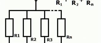
Consider a circuit in which resistors are connected in parallel. Let's start with the layout diagram. The marks on the diagram will correspond to the values of the elements:
- B1 is a battery holder, the nominal voltage on each element is 1.5 V, a total of 6 V
- R1 - 22 kOhm resistor (red/red/orange/gold stripes)
- R2 - 10k ohm resistor (brown/black/orange/gold stripes)
- R3 - 2.2 kOhm resistor (red/red/red/gold stripes)
Let's assemble the circuit on a breadboard. What will be the total resistance Rс of all resistors in the circuit? Before answering this question, please note that only R1 and R2 are connected in parallel. At first we will deal only with them. The formula for the total resistance of parallel connected resistors is:
We recommend reading: How to measure resistance with a multimeter: instructions, photos, videos
R 1,2 = (R1 x R2) / (R1 + R2) R 1,2 = (22 kOhm x 10 kOhm) / (22 kOhm + 10 kOhm) R 1,2 = 220 kOhm / 32 kOhm R 1,2 = 6.9 kOhm R 1.2 = 6900 Ohm
The total resistance of R1 and R2 is 6.9 kOhm. Now let's look at the circuit again - resistors R1 and R2 are connected in series with resistor R3. Simplifying the diagram will highlight:
Consecutive stages of circuit conversion: a) view of the original circuit, b) circuit of the equivalent circuit after replacing two branches with one replacement branch with resistance R1.2, c) circuit of the equivalent circuit after replacing resistors R1.2 and R3 with resistor Rc.
Note that when replacing the original circuit diagram, the equivalent voltage and current in the unconverted part of the circuit must remain unchanged.
Returning to the topic: since resistors R1 and R2 are connected in parallel and in series with resistor R3, it is enough to add the resistance R 1.2, just calculated using resistor R3, to get the total resistance Rc:
Rc = [(R1 * R2) / (R1 + R2)] + R3 Rc = R 1.2 + R3 Rc = 6.9 kOhm + 2.2 kOhm Rc = 9.1 kOhm Rc = 9100 Ohm
We know how to calculate the impedance of a circuit. Remember that you calculated it based on the nominal resistance values of the resistors used. As an exercise, we suggest calculating the actual impedance in your circuit in the same way (after measuring the resistance of all resistors with a multimeter). For this case it is 9.1 kOhm.
To calculate the current, you need to know the voltage supplied by the battery:
Left: multimeter connection diagram, right: measuring voltage on both sides of the battery
In this circuit, the battery, that is, the voltage source, provides the circuit with a voltage of 6.10 V. Let's calculate the current I:
I = U / Rc I = 6.10 V / 9100 Ohm I = 0.00067 A = 0.67 mA = 670 µA
Now let's look at the voltage in the circuit by placing the meter probes in different places:
Left: multimeter connection diagram; right: measuring the voltage drop across resistor R1
Left: multimeter connection diagram; right: measuring the voltage drop across resistor R2
Left: multimeter connection diagram; right: measuring the voltage drop across resistor R3
The battery supplies the circuit with a voltage of 6.10 V. Interestingly, the voltage drop across the resistors connected in parallel is the same (4.60 V each), although they have different resistances. The drop across R3 is 1.49 V.
Will we get the same values from the calculations?
U R1.2 = I x R 1.2 U R1.2 = 670 µA x 6.9 kOhm U R1.2 = 4.62 V U R3 = I x R3 U R3 = 670 µA x 2.2 kOhm U R3 = 1 .47 V
The results came out almost identical.
Now let's measure the current at individual points of the circuit:
Left: diagram of connecting the ammeter to the circuit; right: current measurement I
Left: diagram of connecting the ammeter to the circuit; right: current measurement I1
Left: diagram of connecting an ammeter to a circuit; right: current measurement I2
The battery provides 6.10 V of voltage in a closed loop where a current of 670 μA flows. The current (we can think of it as electrons flowing) is divided into two branches: some of the electrons flow through the branch labeled I1, and some through the I2 branch. At the second node, branches I1 and I2 are again connected to give current I. Here we arrived at Kirchhoff’s first law: for each node in an electrical circuit, the sum of the currents flowing into the node is equal to the sum of the currents emanating from the node. In our case:
I = I1 + I2
Let's see if the calculated current is the same as the measured one:
I1 = U R1 / R1 I1 = 4.62 V / 22 kOhm I1 = 210 µA I2 = U R2 / R2 I2 = 4.62 V / 10 kOhm I2 = 460 µA I = I1 + I2 I = 210 µA + 460 µA
The experimentally obtained results are very similar to the calculations obtained, which perfectly shows the connection between theory and practice in radio electronics.
In general, that’s all for today, it’s not easy to cover the vast world of electronics in one material, and it takes time to master all the information received. Then go to the section on circuits for beginners and try to assemble simpler devices, and any questions you may have can be clarified on the forum. Good luck!
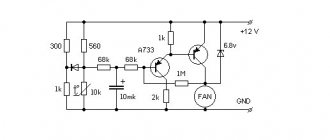
Automatic cooler speed controller
This device will be useful both for ordinary people and for PC repair and maintenance specialists. Often, manufacturers of computer components directly connect the power to the cooler that cools the processor or motherboard. This causes the device to continuously spin at maximum speed even though the PC is idle. By installing a homemade automatic regulator, you don’t have to worry about the processor temperature, because the sensor will turn on the cooling automatically when it’s really needed.
You might be interested in Homemade conductive glue
Device diagram
The speed controller will not only increase the service life of the cooler, but also reduce the noise level in the room. It can be made using two transistors, a resistor and a thermistor.
Homemade product in the form of a cooler regulator
Conventional graphic symbol
The basis of any electronic device is radio components. These include resistors, LEDs, transistors, capacitors, various microcircuits, etc. To learn how to read electrical circuits, you need to know well the graphic symbols of all radio components.
For example, consider the following drawing. It consists of a battery of galvanic cells GB1, resistor R1 and LED VD1. The conventional graphic designation (UGO) of the resistor looks like a rectangle with two terminals. In the drawings it is designated by the letter R, followed by its serial number, for example R1, R2, R5, etc.
Since an important parameter of a resistor, in addition to resistance, is power dissipation, its value is also indicated in the designation.
The LED UGO has the shape of a triangle with a line at its apex; and two arrows, the tips of which are directed from the triangle. One terminal of the LED is called the anode, and the second is called the cathode.
An LED, like a “regular” diode, passes current in only one direction - from the anode to the cathode. This semiconductor device is designated VD, and its type is indicated in the specification or in the description of the circuit. The characteristics of a particular type of LED are given in reference books or “datasheets”.
Power supplies
To indicate a simple power source, a symbol consisting of 2 lines separated by a space is used. Thin long characterizes the positive pole, and short thick characterizes the negative pole. In addition, the pole designation is placed next to the lines. If you need to depict a battery consisting of several galvanic cells, then 2 symbols for the power source are connected by a short dotted line.
Wires and their connections
Conductors are indicated by thin horizontal or vertical lines. Deviation at a straight or obtuse angle is allowed. If the wires intersect, the connection point is marked with a dot.
For easier reading, such symbols may be colored. Cables are symbolized by thicker lines.
Common wire
To simplify the drawing and reading of the PS, the common wire designation is used. It represents an inverted letter "T". Its vertical crossbar is connected to all the wires, which are connected to a point with negative potential.
Radio components
Each radio component has its own designation, approved by GOST or other standards. Thanks to this, uniformity of design is achieved.
Chip
A chip (U) is a circuit that is manufactured on a wafer or film. Typically, the material for a microcircuit is silicon. The chip is not a collapsible element. At the same time, some technicians manage to identify a radio component that is in a short circuit, for example, in a non-separable Wi-Fi chip.
Resistors
Resistor (R – designation in the diagram) – for linear conversion of current to voltage and vice versa. And also to limit the current in an electrical circuit. Instead of a resistor with zero resistance, it is allowed to install a jumper, only for the duration of diagnostics. After carrying out troubleshooting activities on the phone board, install R in its place in the circuit. If the resistor is damaged, take it from the “donor” board.
We recommend reading: Varistor: principle of operation, main characteristics, designation on the diagram
Capacitors
Capacitor (C) is a radio component designed to accumulate charge. In circuit design, another important property of a capacitor is used - it quickly releases a charge (discharges) when the consumer of electrical energy is turned on. In order to check the capacitor for a short circuit, you need to remove it from the circuit and take measurements with a multimeter in continuity mode. The capacitance of a capacitor depends on several factors. One of them is the geometric dimensions of the capacitor plates. In iPhone 6, if the backlight unit malfunctions, a short circuit on capacitors C1530, C1531, C1505 occurs when the board is connected to the LBP.
Coil
Coil (Fl) - filter or fuse - is designed to protect the circuit from the effects of high currents. It is a self-destructive element and is used to disconnect the closed circuit by opening it. The filter is checked with a multimeter in the circuit test mode for integrity.
Diodes
Diode (D) – conducts electric current in one direction. That is, if during measurements, the diode passes current in the opposite direction, then it is faulty. Used in the phone backlight unit. Structurally, it has 3 outputs. Anode and two cathodes. The diode is checked for serviceability with a multimeter in diode testing mode.
The polarity of the diode can be determined:
- key (tag) on the cathode,
- multimeter in diode testing mode,
- visually, on an unsoldered “donor” board.
Acoustic morgalik
The operating principle of acoustic devices is always associated with capturing human sounds and voices using a microphone. When sound waves hit the sensitive elements of the speaker, they are converted into an electrical signal, which causes the LEDs on the board to “blink”. The circuit consists of the following radio elements:
- Two KT315B transistors;
- Resistors (3 pieces) at 4700 Ohm, 1 MoMb, 10 kOhm;
- Microphone;
- Polar type capacitors (2 pieces) 47 and 1 µF;
- 3 Volt LEDs in the amount of 6 pieces.
You might be interested in this: Generator connection diagram
Morgalik scheme
The device functions as follows: an amplifier that increases the frequency of sound vibrations, when sound waves hit it, begins to change its resistance. The alternating signal passes through the capacitor and enters the transistor, opening it. The current reaches the collector and flows to the second element, which also opens and the light bulbs begin to “blink”.
Morgalik in practice
How to read simple diagrams
The reading process for “dummies” is examined using the example of a simple project consisting of a power source, a bell, a non-locking button and conductors. The circuit is a closed circuit with components connected in series. This means that the strength of the current flowing through it will be the same at any point.
When voltage is applied and the button is pressed, the bell starts ringing. This is because current flows from the positive terminal of the battery to the negative terminal through all components. If the wires do not resist direct current, then the voltage at the bell terminals and the power supply terminals will be the same according to Kirchhoff’s second law.
Circuit breaker
The circuitry of the device is extremely simple, but very reliable. The operating principle of the switch is based on the operation of a capacitor. When a button is pressed, the LED or lamp lights up. When the capacitor is completely discharged, the light source will go out. The operating principle is as follows: when you press the return button, the capacitor is charged and it turns into a “nutrient” element. When the switch opens the contact, the radio element will discharge and power the circuit in which the lamp is installed.
You may be interested in Installing a motion sensor
Electrical diagram of the switch on the button
Important! Since a capacitor cannot hold a charge forever, the light will sooner or later go out. It is difficult to say when this will happen, since everything depends on the characteristics of the radioelements used in the device.
Such a device would be useful, for example, in a cellar or technical underground. A person presses a button, takes the things he needs and, in order not to reach for the switch with a load in his hands, simply leaves the basement. When the capacitor is completely discharged, the light bulb will go out.
Assembled switch
How to learn to read circuit diagrams
There are really only a few ways. This is theory and practice. If you learn the designation of radio components, this does not mean that you have learned circuit design. It's like learning your ABC's, but without grammar and practice you won't learn the language.
Theory is circuit design, books, a description of the principle of operation of the circuit. Practice involves assembling devices, repairing and soldering.
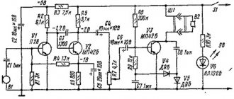
For example, a simple amplifier circuit with one transistor.
Input X1 plus (left or right channel), X2 minus. The sound signal is sent to electrolytic capacitor C1. It protects transistor VT1 from short circuiting, since transistor VT1 is constantly open using a voltage divider across R1 and R2. The voltage divider sets the operating point at the base of transistor VT1, and the transistor does not distort the input signal. Resistor R3 and capacitor C2, which are connected to the emitter of transistor VT1, perform the function of thermal stabilization of the operating point as the temperature of the transistor increases. Electrolytic capacitor C3 accumulates and filters the supply voltage. The BF1 dynamic head serves as an audio signal output.
Is it possible to understand this only by learning the designations of radio components without circuit design and theory? Unlikely.
The situation is even more complicated with digital technology.
What kind of microcontroller is this, what functions does it perform, what firmware and what fuses are installed in it? And the second microcircuit, what amplifier is it? Without datasheets and a description of the circuit, it will not be possible to understand its operation.
Study circuit design, theory and practice. Simply learning the names of the parts will not help you understand the circuitry. The designation of radio components can be learned on its own with practice and accumulation of knowledge. It all depends on the chosen industry. Signalmen have one circuit design, mobile equipment repairmen have another. And those who deal with sound will not really understand electricians. As well as vice versa. To understand another industry, its circuitry and operating principles, you need to immerse yourself in it.
Circuit diagrams are a kind of language that has different dialects.
Therefore, one should not create illusions. Study circuit design and assemble circuits.
Schematic diagrams help to assemble devices, and when studying the theory, to understand the operation of the device. Without knowledge and experience, a diagram is just a diagram.
What letters indicate radio components in the diagrams?
| Letter designation on the diagram | Radio component |
| R | Resistors (variable, trimmer and constant) |
| V.D. | Diodes (zener diode, bridge, varicap, etc.) |
| C | Capacitors (non-polar, electrolytic, variable, etc.) |
| L | Coils and chokes |
| S.A. | Switches |
| F.U. | Circuit breakers |
| F.V. | Arresters |
| X | Connectors |
| K | Relay |
| VS | Thyristors (tetrode, dinistors, photothyristors, etc.) |
| VT | Transistors (bipolar, field-effect) |
| H.L. | LEDs |
| U | Optocouplers |
Ratings of radio components
In general, there are disagreements in this regard. According to GOST at the moment, the nominal values of parts are not indicated on circuit diagrams. This is done in order not to clutter the diagram with information.
The circuit diagram is accompanied by a list of parts, wiring and structural diagrams, as well as a printed circuit board.
There is another generally accepted standard. The diagrams indicate the ratings of some parts and their operating voltages.
For example, in this circuit there are two resistors.
By default, resistance without a prefix is written only as a number. R2 has a resistance of 220 Ohms. And R3 has a letter after the number. The resistance of this resistor reads 2.2k ohms (2,200 ohms).
Consider two capacitors in the diagram.
In this case, C5 is a non-polar capacitor with a capacitance of 0.01 µF. Microfarads can be designated either uF or uF. And capacitor C6 is polar and electrolytic. This is indicated by the plus sign near the UGO. Capacitance C6 is 470 μF. The rated operating voltage is indicated in volts. Here for C6 it is 16 V.
Nanofarads are denoted as nF.
If there is no microfarad (uF) or nanofarad (nF) prefix on the circuit, then the capacitance of this capacitor is measured in picofarads (pF, pF). This condition is not common, so carefully study the diagram you are about to read or assemble. There are few capacitances in farads (F), so µF, nF and pF are used.
Hidden wiring detector
A hidden wiring indicator is a special device for detecting an electrical network laid in grooves under the plaster of a wall. Even simple repairs to home electrical wiring and sockets cannot be done without it. The device is necessary when the old wiring in the walls was laid without executive circuits, and it is impossible to determine the location of its installation in the absence of a special device. When performing repair work, the integrity of the insulation of hidden wiring may be damaged by a drill or nail. Such actions can cause electric shock and also disable the entire home network.
Detector chip for hidden wiring
To detect hidden wiring, in most cases, a device made of a pointer or digital ohmmeter with a field-effect transistor will be sufficient. The body of the radio element is passed along a section of the wall and, if it “sees” the wiring, the values on the ohmmeter immediately change. The modified detector is shown in the diagram below. To make it you need:
- Battery;
- LED for indication;
- Transistor;
- Resistors: 1 Mohm, 100 kOhm, 330 Ohm and 220 Ohm;
- Switch to start working.
Detector parts