The simplest radio receivers are not suitable for catching the FM range, frequency modulation. Common people say: this is where the name comes from. In English we interpret the letter FM as frequency modulation. A clearly expressed meaning is important for readers to understand: the simplest radio receiver, assembled with your own hands from rubbish, will not accept FM. The question of necessity arises: the cell phone picks up the broadcast. Electronic equipment has a similar capability built into it. Far from civilization, people still want to catch broadcasts the old-fashioned way - they almost said with dental crowns - by constructing efficient devices for listening to their favorite programs. For free…
Preparatory stage
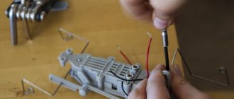
Before mastering the correct techniques for handling solder and a soldering iron at home, you should take a special course that includes training in soldering and everything that precedes this procedure.
You can study on your own, but when mastering the work with jewelry and complex electronic circuits, you cannot do without an experienced mentor. From the point of view of organizing the process, soldering metals using special solders is a set of operations that are quite simple in content. However, despite the apparent ease, not everyone can solder correctly the first time. When you first meet, some difficulties arise due to the lack of a clear idea of what needs to be done and in what order.
It is recommended to follow certain rules for preparing for soldering operations, the essence of which boils down to the following:
- it is necessary to correctly select the main working tool that will be used for soldering;
- you should worry about making a convenient and functional stand, prepare a place where you will have to solder most of the time;
- the student must stock up on suitable consumables, without which no such procedure can be completed (solder, liquid or paste flux).
And finally, a novice user must master the basic soldering techniques, which require a certain sequence of targeted actions.
You can solder with an electric soldering iron, gas torch or blowtorch. It is customary to solder boards and microcircuits with special hair dryers and thermal stations that ensure uniform heating. The choice of a particular type of tool and a stand or holder for it is determined by the temperature conditions under which work operations are expected to be carried out.
The next requirement in order involves the preparation of the required components that allow you to correctly solder any metal connection. These usually include various types of solder, flux additives and special soldering liquids necessary to improve its quality (rosin and alcohol compounds for tinning).
All components of the process must be selected for the specific conditions of formation of the solder joint and taking into account the characteristics of the parts used.
So, what do you need to make a walkie-talkie?
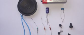
To create a walkie-talkie you will need the following items:
- 4 MP-42 transistors and 3 P416B transistors;
- Resistors. You will need a lot of them: two pieces each. 3K, 160K, 4.7K, one each – 22K, 36K, 100K, 120K, 270K, and six pcs. 6.8 K;
- Capacitors: two 10 MK 10 V, 3300, 1000, 100, 6, 5-20, 22, 10 and one 5 MK 10 V – 4; 0, 0, 47 MK.
- Telescopic antenna;
- Microphones and speakers;
- Textolite boards - 2 pcs.
- Soldering iron;
- Socket;
- Wire cutters.
Almost all of the above is included in the special kit for radio amateurs JC986A. The further algorithm will be based on this set.
It is worth considering that creating your own walkie-talkie requires skills in working with a soldering iron and knowledge of how to determine the values of the elements.
Basic operating procedures
The technological map or diagram of “correct” soldering using a soldering iron assumes the following order of operations.
Before directly soldering, the surfaces of the objects to be soldered are cleaned of heavy dirt and corrosive deposits, after which they should be cleaned to a characteristic shine.
After this, the places where the parts are soldered are treated with a previously prepared flux, through which it is possible to improve the conditions for the spreading of solder over the contact surface.
Then the contact pad or soldering zone is subjected to protective tinning, the essence of which is to apply solder melted to a liquid state on them. In this case, the consumable material spreads evenly over the surface of the parts that need to be soldered and ensures the formation of a reliable thermal connection.
When preparing parts for tinning, preference is given to paste-like fluxes, which are convenient to apply and easy to wash off. Before processing and soldering, the parts are pre-connected by mechanical twisting or compression with pliers.
After fixing, flux is applied to them again, and then the contact area is heated while simultaneously introducing a solder rod into it (its composition may differ from the material used for tinning).
It is impossible to learn how to solder correctly with your own hands unless you learn how to tin a soldering iron tip. For tinning, after the soldering iron has completely warmed up, the working tip should be pressed firmly against any foil-covered surface and rubbed over the molten rosin with solder.
This operation should be repeated until a characteristic film of solder appears on the edges of the copper tip, ensuring good adhesion to any metal.
The question of how to solder correctly comes along with an interest in why soldering is needed and what can be done with it. Previously, it was mainly pots and samovars that were soldered, but today you can also solder high-tech things.
Settings
Tuning a radio station begins with the radio receiver. By rotating the core of coil L3, the characteristic noise of a super-regenerator appears in the BA1 dynamics. E
If this cannot be achieved, then select the capacitance SZ. After the super-regeneration mode appears, its safety is checked with a power supply of 7.9 V and different lengths of the WA1 antenna.
Sometimes it may be necessary to select a more precise value for resistor R6. To configure the L3, C1 circuit, use a model radio station having a range of 27.140 MHz in transmit mode. By rotating the core of coil L3, they try to tune in to the signal of a model radio station. This completes the radio station setup.
Soldering capabilities
There are more than enough opportunities to use your ability to correctly solder metal parts and products. This method is used to carry out many assembly and repair operations. Here are a few particularly important ones:
- you can solder copper tubes that are part of the internal lines of heat exchangers and refrigeration units;
- solder elements of various electronic circuits;
- carry out repairs, soldering of jewelry, glasses;
- fix carbide cutting inserts on metalworking tool holders;
- in everyday life, soldering is also often used when it is necessary to fasten flat copper parts on metallized surfaces of sheet blanks;
- the ability to tin high-quality surfaces can be useful for protecting metal structure elements from corrosion.
At the initial stage of learning the art of soldering, it is recommended to use the simplest circuits of electronic devices.
In addition, through the process under consideration, it is possible to solder parts from metals of dissimilar structures, as well as seal various types of rigid connections.
Preparation for activities
In this paragraph we will tell you how to create your own radio. When the necessary documents are completed, it’s time to register the media and begin developing the frequency. To do this, you will need to write an application for its provision. At all these stages, it is advisable to consult with a lawyer in order to make the best decision.
Before attempting to obtain a frequency, it is necessary to prepare information regarding what power the transmitter will be used, where it is intended to be located, and where the radio station itself will be located.
When calculating possible prospects, it is worth taking into account the fact that you cannot buy a radio frequency, since it is a state resource. It is not sold as a product, but is played out in a competition between applicants. In this regard, it may happen that someone else receives the frequency.
If this happens, don't despair. Sometimes the competition is won by the one who currently does not plan to carry out his own broadcasting on the received frequency. In this case, the conversation about renting it will be relevant.
Types of soldering operations
The variety of soldering methods is explained by many different factors that determine the quality and efficiency of its implementation.
Such factors include not only the type of soldering device and the type of solder that is used in the process, but also the technological features of the formation of the seam. To surface mount parts on a board, you need to learn how to use a solder mask correctly. In any case, in order to solder correctly, you need to know the melting temperature of the metal you are working with. It affects the choice of soldering tools, as well as fluxes and solder. In accordance with the specified parameter, solder materials are divided into low-melting (up to 450 degrees) and refractory (more than 450 degrees).
Necessary first steps before opening
The first thing to start with is completing the necessary documentation. First of all, you need to open a legal entity, for example, a company, the charter of which will indicate the following types of activities:
- creation of television and radio projects;
- advertising of a commercial and political nature;
- television and radio broadcasting;
- activities related to the media;
- the possibility of purchasing studio space for radio stations and various facilities used for radio broadcasting.
Simple two-transistor direct amplification radio receiver
A simple direct amplification receiver is shown in Fig. 1 [MK 10/83-11]. It contains a tunable input oscillatory circuit - a magnetic antenna and a two-stage low-frequency amplifier.
The first stage of the amplifier is also a detector of the RF modulated signal. Like many similar simple direct amplification receivers, this receiver is capable of receiving signals from powerful, not so distant radio stations.
The inductor is wound on a ferrite rod 40 mm long and 10 mm in diameter. It contains 80 turns of PEV-0.25 mm wire with a tap from the 6th turn from the bottom (according to the diagram).
Rice. 1. Circuit of a simple radio receiver with two transistors.
How to assemble a simple radio receiver?
There are several radio receiver circuits:
- detector;
- direct amplification;
- (super) heterodyne;
- on a frequency synthesizer.
Receivers with double and triple conversion (2 or 3 local oscillators in a circuit) are used for professional work at the maximum permissible, ultra-long distances.
The downside of the detector receiver is low selectivity: signals from several radio stations can be heard simultaneously. The advantage is that there is no separate power supply: the energy of the incoming radio waves is enough to listen to the air without powering the entire circuit. At least one repeater must be broadcasting in your area - in the range of long (148-375 kilohertz) or medium (530-1710 kHz) frequencies. When you are 300 km or more away from it, you are unlikely to hear anything. It should be quiet around - it is better to listen to the program using headphones with high (hundreds and thousands of ohms) impedance. The sound will be barely audible, but both speech and music will be understandable.
The detector receiver is assembled as follows. The oscillating circuit consists of a variable capacitor and a coil. One end of it is connected to an external antenna. Grounding is supplied through the building circuit, and the heating network pipes are supplied to the other end of the circuit. Any RF diode is connected in series with the circuit - it will isolate the audio component from the RF signal. A capacitor is connected to the resulting assembly in parallel - it will smooth out the ripples. To extract sound information, a capsule is used - the resistance of its winding is at least 600 Ohms.
If you disconnect the earphone from the DP and send a signal to a simple audio amplifier, then the detector receiver will become a direct amplification receiver. By connecting a MF or LW radio frequency amplifier to the input - to the circuit - you will increase the sensitivity. You can move up to 1000 km from the AM repeater. A receiver with a simple diode detector does not work on the (U) HF band.
To improve adjacent channel selectivity, replace the detector diode with a more efficient circuit.
To ensure selectivity in the adjacent channel, a local oscillator, a mixer and an additional amplifier are needed. A local oscillator is a local oscillator with a variable circuit. The heterodyne receiver circuit works as follows.
- The signal comes from the antenna to a radio frequency amplifier (RFA).
- The amplified RF signal passes through a mixer. The local oscillator signal is superimposed on it. A mixer is a frequency subtractor: the local oscillator value is subtracted from the input signal value. For example, to receive a station on 106.2 MHz in the FM band, the local oscillator frequency must be 95.5 MHz (10.7 remains for further processing). The value 10.7 is constant - the mixer and local oscillator are adjusted synchronously. Mismatch of this functional unit will immediately lead to the inoperability of the entire circuit.
- The resulting intermediate frequency (IF) of 10.7 MHz enters the IF unit. The amplifier itself performs the function of a selector: its bandpass filter cuts the spectrum of the radio signal to a band of only 50-100 kHz. This ensures selectivity on the adjacent channel: in the densely packed FM range of a large city, radio stations are located every 300-500 kHz.
- Amplified IF is a signal that is ready to be transferred from the radio frequency region to the audio frequency region. The amplitude detector converts the AM signal into audio, highlighting the low-frequency envelope of the radio signal.
- The resulting sound signal is sent to a low-frequency amplifier (LF) - and then to a speaker (or headphones).
The advantage of the (super) heterodyne receiver circuit is satisfactory sensitivity. You can move tens of kilometers away from the FM transmitter. Selectivity on the adjacent channel will allow you to listen to the radio station you like, and not to the simultaneous cacophony of several radio broadcasts. The disadvantage is that the entire circuit requires power - several volts and up to tens of milliamps of DC.
There is also selectivity along the mirror channel. For AM receivers (LW, MW, HF bands) the IF is 465 kHz. If in the CB range the receiver is tuned to a frequency of 1551 kHz, then it will “catch” the same frequency at 621 kHz. The mirror frequency is equal to twice the IF value subtracted from the transmitter frequency. For FM (FM) receivers operating in the VHF band (66-108 MHz), the IF is 10.7 MHz.
Thus, a signal from an aviation radio (“mosquito”) operating at 121.5 megahertz will be received when the receiver is tuned to 100.1 MHz (minus 21.4 MHz). To eliminate the reception of interference in the form of a “mirror” frequency, an input circuit is connected between the RF amplifier and the antenna - one or more oscillating circuits (a coil and a capacitor connected in parallel). The disadvantage of a multi-circuit input circuit is a decrease in sensitivity, and with it the reception range, which requires connecting an antenna with an additional amplifier.
The FM receiver is equipped with a special cascade that converts FM into AM waves.
The disadvantage of heterodyne receivers is that the signal from the local oscillator without an input circuit and in the presence of RF feedback enters the antenna and is re-radiated into the air. If you turn on two such receivers, tune them to the same radio station, and place them side by side, close together, a slight whistling of a changing tone will appear in the speakers of both. In a circuit based on a frequency synthesizer, a local oscillator is not used.
In FM stereo receivers, after the amplifier and detector, there is a stereo decoder. Stereo signal encoding at the transmitter and decoding at the receiver is carried out using pilot-tone technology. After the stereo decoder, a stereo amplifier and two speakers are installed (one for each channel).
Receivers that do not have stereo decoding function receive stereo broadcasts in monaural mode.
To assemble the receiver electronics, do the following.
- Drill holes in the workpiece for the radio board, checking the drawings (topology, arrangement of elements).
- Place radio elements.
- Wind the loop coils and magnetic antenna. Place them according to the diagram.
- Draw the tracks on the board, checking the topology from the drawing. Paths are made both by cutting and etching.
- Solder the parts onto the board. Check the correct installation.
- Solder wires to the antenna input, power supply and speaker output.
- Install controls and switches. A multi-range model will require a multi-position switch.
- Connect the speaker and antenna. Turn on the power supply.
- The noise of an untuned receiver will appear in the speaker. Turn the tuning knob. Tune to one of the available stations. The sound of the radio signal should be free of wheezing and noise. Connect an external antenna. You need to adjust the coils and shift the range. Choke coils are adjusted by rotating the core, frameless coils are adjusted by stretching and compressing the turns. They require a dielectric screwdriver.
- Select an extreme frequency on the FM modulator (for example, 108 MHz) and move the turns of the local dyne coil (it is located next to the variable capacitor) so that the upper end of the receiver range stably receives the modulator signal.
Assemble the body:
- Mark and cut plywood or plastic into 6 edges of the future body.
- Mark and drill holes for the corners.
- Cut out a large round gap for the speaker.
- From the top and/or side, cut out slots for the volume control, power switch, band switch, antenna and frequency control knob, guided by the assembly drawing.
- Install the radio board on one of the walls using “pile” type screw racks. Align the controls with the technological holes on the adjacent sides of the housing.
- Mount the power supply - or USB board with lithium-ion battery (for the mini radio) - away from the main board.
- Connect the radio board to the power supply board (or to the USB controller and battery).
- Connect and secure the magnetic antenna for AM and the telescopic antenna for FM. Securely insulate all wire connections.
- If a loudspeaker model is being manufactured, install the speaker on the front edge of the case.
- Using the corners, connect all the edges of the body to each other.
For the scale, calibrate the adjustment knob and place a mark in the form of an arrow next to it on the body. Install an LED for illumination.
8 photos
Recommendations for beginners
- To avoid overheating diodes, transistors and microcircuits, do not use a soldering iron with a power of more than 30 watts without flux.
- Do not expose the receiver to precipitation, fog, frost, or acid fumes.
- Do not touch the high voltage terminals of the power supply when the device under test is energized.
Instructions
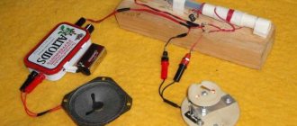
We will assemble the radio according to a proven scheme:
A1 – common antenna for receiving and sending a signal SA1 – power switch SA2 – switch connecting the power source and the radio station.
1. Making coils:
a. To make a cylindrical base with a diameter of 0.8 cm and a height of 2 cm, plexiglass, polystyrene or cardboard. b. We wrap the base with copper wire with a diameter of 0.5 mm in tight turns. c. We wind ten turns on coils d. We will wind coils L2 and L3 on the same base, observing the conditions: e. We wind four turns onto coil L2 . f. We place L2 between the windings of L3. g. L3 will consist of 8 turns with a wire outlet in the middle. h. Coils L4 and L6 each contain 200 turns . i. For the winding, we take a wire with a diameter of 0.1 mm j. We wind it around the body of an MLT-0.5 type resistor with a resistance of more than 1 MOhm.
2. The result should be as shown in the figure:
3. Now we prepare the printed circuit board 4. We arrange the radio components according to the diagram.
5. We make a printed circuit assembly from foil getinax. 6. We make a frame from centimeter-long scraps of copper wire inserted into holes with a diameter of about one millimeter.
Now you need to configure the radio:
1. We begin debugging by improving the signal:
a. 33-47 kOhm variable resistor . b. We achieve the loudest noise possible. c. We change the inductance level of coil L5 by adjusting the core. d. We are trying to improve the signal. e. We replace the connected variable resistor with R10 with the required resistance.
2. If the voice timbre is distorted during signal transmission, we select resistors R1 and R3 more carefully.
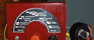
3. We debug the generator and antenna using a wave meter; its electronic circuit is shown below. Wave meter:
4. For the L1 wavemeter coil of ten turns of 1.2 mm wire, we use a frame with a diameter of 22 mm, the third turn from the bottom serves as a tap. 5. Capacitor C1 of the wavemeter must be made variable. 6. We place handle C1 of the wave meter opposite the current frequency of the radio. 7. Place the wave meter so that next to the L3 coil of the radio there is a L1 wave meter coil. 8. Thus, we make it a kind of indicator. 9. Instead of the C9 radio, we try capacitors of different capacities. 10. We achieve the maximum deviation of the wave meter needle. 11. We bring the wave meter to the antenna. 12. Rotate the L1 coil core of the radio. 13. We bring the antenna into resonance with the circuit frequency, tuning L3, C8 and C9. 14. We achieve the maximum deviation of the wave meter needle.
Audio transmitter
In this article I want to introduce a music transmitter
.
I tried to assemble a radio transmitter using a varicap in the modulator. Since it was needed to transmit an audio signal and not a conversation, I installed a plug instead of a microphone. Coil of 9 turns of wire with a diameter of 1 mm
, the middle tap is sealed. I pushed a small piece of foam rubber inside the coil and dripped it with paraffin (a candle) so that the coil would not bend when touched, because the frequency depends on this, and it is very easy to knock it down.