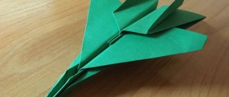
Model airplane made from ceiling tiles
Which boy doesn't admire structures like airplanes? Do-it-yourself aircraft models made from ceiling tiles are an excellent gift for children who are interested in aviation. Especially if they took part in assembling the airframe. The article will tell you how to make a simple airplane model from ceiling tiles.
Posts tagged “ceilings” - parkflyer
As a child, I was always drawn to airplanes; I remember the first rubber engine built based on some pictures from Soviet MK magazines. Then everything seemed to fade away. Many years later, having already had my own small business and some free time, I remembered my old dream of a radio-controlled flight, but by that time I had no experience in construction yet, and there were problems with the Internet. And then by chance in my city I came across a store that sold a radio-controlled Cessna aircraft with a span of approximately 1200mm. Without hesitation I bought it and assembled it. There was no one to consult with; I did everything and configured it as I saw fit, starting from a rather meager amount of knowledge in aircraft modeling. After probably 20–30 attempts at uncontrolled flight, I realized that either this model was not destined to fly, or “my skis don’t work,” and besides, the model was badly damaged. I set up the Internet, searched through various technologies, pictures, diagrams and drawings and made a decision, which was not easy for me, to remove all the electronics from the Tsesna and assemble my own model using the spare parts received. In the end, I was not mistaken; the new model, made from ceiling tiles and scraps of foam plastic from the TV packaging, took off and flew smoothly, and was controlled adequately and predictably and obeyed control. I experienced indescribable delight and even pride that I could still do something. All year I launched my plane and was happy. The plane stayed in the air perfectly thanks to the V wing, was light in weight and was capable of performing almost any aerobatics. It was on this that I gained my first piloting experience and everything else. What did I do with him! Since then, I have had many models, but the first one I made with my own hands is firmly stuck in my memory and warms my soul when I turn on the video clip that I created for the first time from the footage. However, enough words, now you will see everything for yourself...
§
It doesn’t matter what exactly prompted me to build this model... Maybe an inquisitive mind, maybe a desire to understand the intricacies of working with foam material, or maybe the reason was the three-channel equipment I found in my hands from some RTF aircraft. Yes, it doesn’t matter anymore... It was a long time ago...
I won’t even try to remember from which site I downloaded the drawings, but years later, they remained on my hard drive, covered with a virtual cobweb and pixels of dust until today!))))
(metplaner97sm.zip)
Now, I'm posting these drawings here - I'm sure they will be useful to someone!
Well, before you start building this throwing glider, I’ll tell you how I cost it.
Watch about copters: Assembling a homemade quadcopter
Assembly of the structure
Once all the elements are ready, you can begin assembling the product. First of all, on the fuselage, mark the place where the stabilizer will be installed. The corresponding mark is on the drawing, so you can simply transfer it.
Next, use a knife to make a slot along the mark, which should correspond in size to the width of the stabilizer. A small amount of foam glue is applied to the stabilizer and it is installed in place, as shown in the photo above.
The next step to assemble the aircraft is to glue the parts with the cabin on both sides to the base. There should be two of them, and they are distinguished by the presence of a protruding element on top. The glue must be applied in a small layer over the entire plane of the elements to achieve good adhesion.
Parts without a cockpit are glued on top of the elements with an aircraft cabin. There should also be two of them and they differ from the previous ones only in the absence of a corresponding protrusion. This is done in order to increase the overall thickness of the aircraft for better aerodynamics.
Using a cardboard cutout, a mark for the location of the wing is transferred to the aircraft body. A through cut is made using a knife along the mark. Its size should not exceed the thickness of the sheet so that it can be well fixed inside.
The wing is initially not inserted all the way. This is done so that it can be smeared with glue on both sides; only after applying the glue can the wing be aligned the way it should be installed.
In order for the model to have better aerodynamics, it is necessary to get rid of sharp corners. A stationery knife and fine sandpaper will help with this. First of all, the corners are carefully cut with a knife. The layer should be minimal so as not to damage the structure. After this, you need to sand the product with fine sandpaper to give it a finished look.
The model will be launched using a special fixture. Therefore, it is necessary to make a small trigger for it. To do this, you will need a piece of skewer, which is fixed directly in front of the wings at an angle of 45 degrees.
The nose of the aircraft is additionally covered with glue. This will give it more rigidity, and the front part will not be deformed when dropped. In addition, this will create additional weight for balancing.
The launch catapult is assembled from a fishing elastic band, a small stick and electrical tape.
The elastic band must be folded into a loop, as shown in the photo, and secured to the stick with electrical tape. Before launching the model from the catapult, it is necessary to ensure that the aircraft glides. It is manually run several times to determine which part needs to add weight to make the model glide.
Popular articles Cool wishes for Maslenitsa in verse, SMS and prose
To start the model, you need to insert part of the skewer into the elastic band, tighten it and release it. You need to launch the plane parallel to the ground, this will give lift and it will take off. If you launch it upward, it will fall into the ground. To make the model easier to find after launch, you need to paint it in bright colors that will not blend in with its surroundings. The full assembly video is posted below.
Making a glider from ceiling tiles
MANUFACTURING A GLIDER FROM CEILING TILES
Korolikhin V.V., additional education teacher, Station of Young Technicians, Glubokovsky district, East Kazakhstan region.
This model is designed for children and teenagers who are beginners to engage in technical creativity circles.
On this model they practice skills in working, balancing the model and launching.
This model can be used for competitions.
You need to start work by making templates.
The drawings indicate: dimensions in millimeters and a scale ruler is attached, arrows indicate the direction of the fibers of the material.
When printing drawings, the dimensions may not match, so they must be adjusted to the specified dimensions.
The width and length of the parts are important; the radii of curvature can be slightly changed.
Master glue and titanium are used to connect parts.
An example of making a fuselage sidewall template.
MANUFACTURING FUSELAGE SIDEWALLS
The side panel part is longer than the ceiling slab, so we glue the workpiece together in two parts.
To do this, cut 3 pieces along the grain, 80 mm wide and long for the entire slab, cut one piece in half.
Making cuts at an angle
We place a short blank with a cutout on the long one and make markings on the long blank.
cut out the wedge, blanks ready for gluing, glued blanks, mark according to the template and
Cut out the sides of the fuselage.
Finished sidewalls, left and right.
The next piece, a strip 40 mm wide and the length of the entire slab,
Curves along the contour of the sidewall.
Glue the insert, control using a square.
Cut out the next insert and glue it to the bottom of the side panel.
The upper insert, from the wide end, is bent along the contour of the sidewall and glued.
The width of the inserts in the nose section is 40mm, from the top bend of the fuselage to the tail section, gradually tapering to 20mm.
The dimensions on the side of the fuselage indicate the width of the insert at a given location. After gluing the sidewall along the contour, a package of ceiling tile plates with a hole with a diameter of 30 mm is glued into the nose part, the hole serves to balance the airframe.
After this, the second side panel is glued.
To fasten the wing in the nose, two slats are installed, oval cross-section 6 mm thick, cardboard washers are used for reinforcement.
The slats are installed 25mm from the top edge
To give the wing a profile, the blank is laid with newspaper sheets and twisted using a pipe with a diameter of 40-50 mm.
Twisting the workpiece
Wing “ears” after twisting to give profile
After giving the profile, the “ears” are cut and the edge of which the “ear” is glued to the wing is ground to give an angle.
The accuracy of the wing assembly is checked on the table by placing the wing on the table and measuring the distance from the end of the “ear” to the surface of the table, the distance should be within 100-90 mm.
A three by five mm strip is glued along the leading and trailing edges of the wing center section.
The dimensions of the wing center section are 130 mm and the entire length of the tile is cut along the grain
The workpiece is cut in half.
Ready assembled glider.
hole for balancing.
There is a hole on the side of the bow for balancing
load, after balancing it is closed with a plug.
Balancing is performed by inserting a weight into the bow through the hole. If the model lifts its nose at launch, you need to add weight, dives sharply, and reduce the weight. A properly balanced model should glide smoothly. The load is fixed with glue.
Schematic model of a glider.
glider toe.
general form
tail unit
Schematic model.
It is made on the basis of the wing from the glider described above; instead of the fuselage, a 10 by 10 mm rail with a length of 700 mm is used.
The toe, made of 10 mm plywood, acts as a weight.
A pylon is glued to the center of the wing to secure the wing to the fuselage.
The pylon is attached to the fuselage using rubber bands.
Balancing is performed by moving the wing along the fuselage.
The sock is made of plywood 10mm thick, 45mm wide, 180mm long.
All homemade products
This model is considered one of the easiest to fly and is therefore suitable for a beginning model pilot, which means it can be used as a trainer. Thanks to such a light material as the ceiling (foam plastic), the model is very light and in case of small falls the damage will not be significant and can be eliminated directly on the airfield.
To make a model airplane you need the following materials:
- Flat (without pattern) ceiling tiles or laminate backing, 3-5 mm thick.
- Glue Titan or any analogue, disposable syringe 5-10 ml.
- Scotch tape of different colors, glue for paper.
- A piece of thin steel wire (for example, a piano wire, wire for a semi-automatic welding machine, etc.), diameter D = 0.8-1 mm.
- A flat base for working with a knife (for example, a sheet of plexiglass, a laminate board).
Required parts:
- Electric motor - for example EMAX CF2822 KV1200 or such A2208 KV1100
- Radio control receiver and transmitter for at least 4 commands, but it is better to immediately take 6 commands. A good budget 4k Flysky fly sky FS-I4 FS-i4 2.4G 4CH RC or more expensive, but almost professional for six commands Flysky FS-i6 2.4G 6CH AFHDS RC transmitter with FS-iA6
- Servos 4 pcs. (look here)
- battery 2200mAh. 11.1 c. or LiPo 4000mAh. at 11.1v
- Propeller size 8040 or 9060
- Flight battery charge indicator
- Charger for LiPo battery
Required tools:1
- Modeler's knife or stationery knife with spare blades.
- Metal ruler 50-100 cm.
- Sandpaper , emery block (stone).
Point 1. Preparation for work.
First you need to find on the Internet, or take here (Easy_Cessna_182) the drawings of the aircraft model itself, then print them on a printer in A4 sheet format.
Lay out the resulting printouts on a flat surface in accordance with serial numbers, the result should be a connected image of the finished elements of the aircraft.
Now you need to glue the necessary sheets together. For proper gluing of sheets, so as not to disturb the dimensions and geometry of the future aircraft, it is necessary to cut off the excess edges on each sheet of the drawing, for the convenience of determining the cutting lines, special border crosses are drawn at the corners, all that remains is to decide which side we will cut, connect the two corner crosses with a line and get cutting line.
After removing the excess sides with scissors, we connect the resulting fragments of the drawing together, evaluate how well everything fits together, after which you can apply glue to the uncut edges of the sheet and glue it together.
The joints must match very precisely.
In this way we glue together all the fragmented elements of the drawing. The result should be seven glued and two single sheets (for the Cessna182 drawing).
Point 2. Cutting blanks.
Important! Ceiling tiles, like the floor underlay, have a laminated front side, and a non-laminated bottom side, only the laminated side can be bent and deformed without fear of breaking in one direction, the non-laminated side cannot be deformed, it will break immediately. Therefore, before you start marking the part, think about which side to place it on the cutting table. The laminated side usually goes to the outside of the model.
So, the drawings are ready, now you can start cutting out these very drawn parts from our ceiling.
Let's prepare the workplace, the work table must be protected from damage to the edge of the knife (cutter), to do this, it is enough to cover the surface of the table with a sheet of flat, fairly hard material, for example, a laminate flooring board or plexiglass, etc. The laminate must be placed face down, because the underside is smooth always, but not always the face.
Now you can lay out a “sandwich” from the backing and the drawing. To make it easier to hold the sheet on the backing, you just need to glue it a little with a pencil. During further manipulations, it will not have time to dry completely and therefore the paper (stencil) from the finished part will be easily removed without being damaged at all for reuse.
Then you can do it in different ways, depending on who you like best.
If the part is simple, with a large number of straight lines, then it is enough to mark all the corners of the part with needle punctures, then remove the stencil paper and, applying a ruler from the puncture point to another point, make a cut with the tip of a knife, then move the ruler to the next points and so on until completed complete cutting of the part.
If the part has a complex shape, with rounded sides, then you can immediately cut using a stencil and completely cut out the workpiece.
In this way, all the parts of the aircraft model are cut out. If you are making your first model, then you need to lay out or mark each of the parts so that you can easily determine its purpose from the drawing.
Point 3. Gluing the aircraft body.
You can start by gluing double partitions, that is, consisting of several identical parts glued together for additional strength.
Like this fuselage partition, for example.
We will use Titanium glue, as it is the most accessible for most beginning modelers, and to apply glue it is convenient to use a syringe without a needle, fill it with glue and use it as a convenient dispenser.
The cut parts are not always smooth enough; this can be easily corrected with sandpaper.
Now we take one side of the fuselage and place it with the correct side on the table so that the laminated side is on the outside of the aircraft. We cut out all the docking and mounting holes in the sidewall, then we put the second half and copy the same holes onto it.
We take the front partition of the compartment, apply glue to the glued side of the workpiece and press it into its installation location, move the workpiece a little in different directions so that the glue is well smeared and again separate the workpieces for 10-30 seconds to dry the glue. (to speed up, you can wave or blow), then connect the parts again and press with force for 5-10 seconds.
Now you can let go and work on other workpieces, periodically checking how the first workpiece is glued and, if necessary, press more.
During the process of building an aircraft, it is important to timely monitor such things as the size of your battery (it may be larger than planned in the drawing) and accordingly independently adjust the dimensions of the compartment if necessary, constantly check the perpendicularity of the parts being glued, do this with a square or ruler.
This is how all the partitions of the front and middle parts of the fuselage are assembled step by step.
When all the partitions are installed, you can glue the second side of the fuselage.
We finish the face and engine mount.
We install the upper fuselage with a slot for the tail.
We glue the tail blanks together, immediately lay in reinforced tape reinforcement for attaching the rudder and toothpicks for rigidity.
We clamp with a board and clamps for gluing.
As a result, everything is smooth and toothpicks do not stand out.
Glue the tail in place.
We always maintain a strict vertical line.
We glue together the parts of the elevator, we also put a bamboo skewer and tape for the steering wheel inside, we perforate the tape with holes for better gluing of the ceiling halves.
We also compress it with a board and clamps until the glue dries completely.
We grind the edges at an angle of 45 degrees so that when the planes are tilted they do not rest against each other; this is convenient to do with a simple stone block.
We mark lines on the wing for gluing the stiffeners.
The wooden axis (spar) is usually made from a 50 cm wooden ruler. If you have a circular saw, you can simply spread the board onto the shingles and then cut it to the required dimensions.
First we glue the spar rail.
In the middle, we reinforce the joint with two more slats.
Then we glue in the foam neurites.
To glue the upper plane of the wing, the ceiling or backing material must be rolled on a piece of pipe to set the bend of the correct shape, after which glue can be applied to all contacting elements and the final gluing can be performed. For fixation while the glue is setting, you can use any of the available ones, weights, clothespins, tape.
Small dents in the field of clothespins can be sanded with sandpaper.
We glue inserts into the central part of the wing.
We mark the ailerons.
We cut through with a cutter on both sides and remove the aileron.
We seal all opened cavities with strips.
The finished ailerons can be glued immediately using reinforced tape or later, when covering the entire model with tape.
The front of the wing can also be reinforced with reinforced tape.
Now you can cover the entire model with tape, this is not only for beauty, but mostly to give it strength; now the model will be able to withstand small falls and impacts.
Iron the tape with a warm iron.
Glue the elevator into place.
To install the elevator wing, you need to make a slot in the body and push the wing into place.
We install servos on the main wing. To do this, we apply and outline them with a marker, then cut out the seat.
The wires can be pulled through using a homemade wire hook.
We install two servos in the fuselage of the aircraft, for the elevator and rudder.
For fastening, you need to use double-sided tape, which is glued to all contact sides of the servo. Then we install them in place and additionally glue the supporting walls.
All that remains is to make a motor mount to mount the motor. It is made from different materials, plywood, plastic, aluminum, polystyrene foam, etc. I had foam plastic from an insulation board, all I had to do was glue two of these pieces together and give them the desired shape.
We glue thin plywood on the motor mounting side; the motor mounting bolts will be screwed into it.
The motor frame is glued into place.
The motor driver is hidden in the front part of the fuselage; the wires are brought out through the ventilation window and connected to the motor wires.
Then, after checking the direction of rotation, you can put the fairing in place and secure it with tape.
Bottom view
The installation site of the wing must be reinforced by gluing thin shingles or plywood.
All that remains is to glue the bottom of the fuselage and cut a hatch to install the battery.
The plane is ready, it's time to fly over.
Usually after the first flight the plane looks like this at best.
But this is all nonsense and can be quickly treated! After 10 falls, only the nose was damaged; the wing was mostly undamaged.
Ceiling glider for little ones
I was sorting out some information on an old propeller and found a selection of drawings for making free-flying gliders.
These aircraft models are easy to make, do not require any skills, and they are not radio-controlled models.
It's just a glider.
The drawings are scans from Polish magazines; in the original they were proposed to be made from balsa, but they would also work great from ceiling tiles.
Actually, this collection of drawings (you can download the glider drawings at the end of the article) is intended for aircraft modeling clubs for children. These still exist in schools.
You can build them just for fun with your child