Device Features
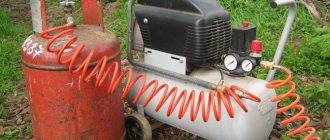
Check valves are used in many applications. Such devices most often work in tandem with some kind of tanks or compressors. The main task of a check valve is to prevent loss of pressure built into the system and limit the access of unwanted elements into the system.
In the absence of such a mechanism, the efficiency of the equipment decreases noticeably. For example, compressors are forced to work almost non-stop, which affects not only the operational life of the equipment, but also electricity bills.
Areas of application for check valves:
In addition to maintaining system pressure, check valves prevent liquid media from entering the compressor. With large volumes of distillation, as well as a serious load on the equipment, it is very important to maintain the tightness of the equipment. This point is also critical when working with gaseous compositions, especially hot ones.
In air conditioning and similar equipment, such valves perform two important functions:
Check valves are often used in ventilation technology, both in domestic and industrial areas. Equipment of this type can be seen in apartments - kitchens and bathrooms, in offices, catering establishments, as well as on construction sites and other technical facilities.
The check valve performs the following functions:
In a similar way, check valves are used in plumbing and other systems where it is necessary to shut off unwanted elements.
Types of equipment
On the market you can find devices of various form factors, as well as purposes. Equipment is usually distinguished by design features, as well as by installation method. The choice of a particular device directly depends on the tasks assigned to it.
Design types of check valves:
The performance of the device is also affected by the material of manufacture. Check valves made of metal alloys are used in industrial structures where heavy loads are expected. Whereas plastic mechanisms can be seen in ordinary kitchens and bathrooms.
Regardless of the design, check valves can be:
The former can often be found in ventilation equipment. Ball valves are used in compressors, and other types are used in gas and plumbing lines. There are also advanced mechanisms with electromagnetic locking.
The cost of the latter, naturally, is noticeably higher. In this case, the blocking occurs not by means of a conventional spring spring, but by means of an electromagnet. But such valves are picky about distillation products and volumes, so manufacturers of industrial equipment most often give preference to more durable and reliable spring analogues.
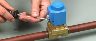
Check valve on compressor
This part is installed between the piston compressor cylinder and the receiver, and prevents air from returning from the storage tank back to the compression chamber after the unit is stopped.
Important! In addition, the return valve, by holding air in the receiver, allows for a smooth start-up of the equipment. If this part is removed, air will press on the piston and the engine will not be able to crank the crankshaft when starting.
In addition to the reverse, a safety valve must be installed on the compressor. This bypass valve is designed for emergency pressure relief if the pressure switch does not turn off the unit engine. The following photo shows the unloading valve, without which, for safety reasons, the compressor cannot be turned on.
Tips for choosing a part
When choosing a check valve for a compressor, you should know the size of the thread cut at the cylinder outlet . The thread may differ in different unit models. The easiest way is to take the faulty part with you and choose a similar one in the store.
If you need to change the return valve, for example, to a more reliable model, you should familiarize yourself with the technical characteristics of the new part. Some of them are not designed to work with high pressure compressors. Usually, the packaging for the return valve indicates the maximum pressure at which it can operate.
The temperature characteristics of this unit should also be taken into account. If the air, after compression, heats up to high temperatures, then you should not buy a plastic unit. Preference should be given to a metal check valve that is installed inside the duct.
Design and principle of operation
The return design includes the following elements (see figure below):
The return, in addition to the inlet fitting, has a side outlet through which it is connected to the receiver, and 1 thin outlet for connecting a pressure switch.
The check valve works according to the following principle. When the compressor is turned on, air passing through the cylinder suction valve enters the compression chamber, after which it exits through the outlet valve and enters the return inlet fitting (7). When a certain pressure is reached, the valve (6) together with the rubber ring rises and compresses the spring (4). As a result, a passage for air opens. The air moves into the housing cavity (3) and then into the outlet fitting connected to the receiver. After turning off the unit, valve (6), under the influence of a spring and air pressure from the receiver, returns to its place and closes the inlet.
How to make a check valve with your own hands
There are situations when the air compressor return valve has failed, and for some reason it is not possible to buy a new part. In this case, the part can be made by hand.
On the Internet you can find quite complex methods for manufacturing this unit using lathes, milling machines and other equipment. But there is still a way to make a simple homemade valve from improvised materials. A drawing of this unit is shown below.
To make a return you will need a metal pipe or tee, a spring, a coupling, a metal threaded plug and a ball.
The air check valve is manufactured as follows.
After this unit is ready, its inlet pipe is connected to the cylinder of the unit, and the second to the receiver.
Source
Compressor valves - what are they?
An air compressor is a unit whose operating principle is based on compressing and supplying air to pneumatic equipment under the required pressure. Such installations are an indispensable element both in everyday life and in industry, being an autonomously functioning technical unit or being included in more complex electrical appliances (for example, climate control or refrigeration equipment). The schematic diagram of any compressor includes a working chamber and a valve system. And since these devices, like any other mechanisms, can break down, you need to know how they are designed, what types of valves there are, how to choose them correctly or make them yourself. More on all this in the material below.
Types and principles of operation of valve mechanisms
Currently, the most common types of compressors are screw and piston units. At the same time, screw compressors, for example, those produced by the Belarusian plant REMEZA, are widely used in various industries, and piston compressors are used in everyday life. The latter can be found both in garages of car enthusiasts (compressors such as SO-7B, Forte VFL-50, etc.) and in life support systems for fish in aquariums (Resun compressors, etc.), as well as in household pneumatic tools.
Piston compressors are characterized by a simple design and a relatively small number of parts and components. There are many different designs of such compressor units, equipped with special plate valves that regulate the process of suction and injection of air during operation . Depending on the purpose of compressor units (their performance, power and operating pressure), three types of valve mechanisms can be found:
Inlet and exhaust valves
Inlet and outlet valve assemblies play such a role in the operation of compressor equipment.
Unloader and safety valves
Thus, the compressor pumps air into the receiver cycle by cycle until the specified pressure value is reached. This process is monitored by a special pressure switch (pressostat), which controls the operation of the electric motor by turning it on and off depending on the degree of air compression. As a rule, the pressure switch also includes a starting unloading valve. A pressure switch is connected between the output of the compressor head and the check valve (return valve), which is connected to the receiver and holds the compressed air there.
Important! The safety valve is responsible for relieving air pressure. Its functions include: ensuring a smooth start of the compressor and preventing the return of compressed air to the compression chamber after the engine is turned off.
The necessary pneumatic equipment is connected directly to the receiver, which can be additionally equipped with various devices (separators, filters, pressure equalizers, etc.).
I made and adjusted the air pressure switch for the compressor myself: find out how
The Russian market offers potential consumers a large number of different tools. Analyzing the state of the market, experts note a slight increase in the popularity of pneumatic tools.
However, while surpassing traditional types of power tools in basic parameters (power, reliability, durability), pneumatic tools require a source of compressed air.
Such a source is an air compressor, the purchase of which for one-time work is not economically feasible. That is why, widely used by professionals, pneumatic tools are rarely used in everyday life.
It is this device that regulates the air pressure in the compressor
Structurally, an air compressor is a device that can be manufactured by a person who has certain knowledge and skills in performing plumbing and electrical work at home. The responsible unit is an air pressure switch (pressostat), which you can install and adjust yourself. In addition, you can independently eliminate the simplest malfunctions of the pressure switch.
Pressure switch: purpose and principle of operation
A pressure switch is a device (actuator) with which the compressor motor is turned on or off. It is mounted on the tank (receiver) and connected to its check valve and the compressor head.
The pressure switch ensures that the entire product operates automatically. With its help, the required air pressure in the receiver is maintained.
The operating principle of such a relay is to use a normally closed contact in the electrical motor control circuit. Depending on the amount of air pressure in the pneumatic system, the power supply circuit is closed or opened. In this case, the engine starts with insufficient air pressure or is de-energized when the maximum value is reached.
As a working mechanism of the pressure switch, springs of different stiffness are used, which react differently to changes in air pressure in the receiver. The actuator is activated due to the forces of elastic deformation of the springs as a result of the pressure of the compressed air located in the receiver. In this case, the contact of the engine power supply circuit is closed or opened.
Accessories
In general, the pressure switch kit includes (maximum configuration):
- Unloading valve.
- Thermal motor protection relay.
- Mechanical switch.
- Safety valve.
The safety valve is an important element of the pressure switch
Each of these devices performs specific functions:
- Unloading valve - opens when the engine is stopped and relieves pressure from the pneumatic line. The next time the electric motor is turned on and accelerates, the check valve is locked, which makes it easier to start the entire device from the off state.
- Thermal motor protection relay - limits the current in the windings. A special adjusting element sets the permissible current strength, exceeding which will lead to shutdown of the electric motor.
- Mechanical switch - turns on the automatic operating mode of the product (AUTO position) and allows you to forcibly turn off the engine (OFF position).
- Safety valve - is activated if the compressor pressure switch fails and produces an emergency release of compressed air from the receiver, preventing pressure from increasing above the permissible value.
Connection diagram
Existing air pressure switches for a 220 V compressor are used in various load connection schemes.
- In the case of using a single-phase electric motor, use a pressure switch with two contact groups, designed to operate in a 220 V network.
- If there is a three-phase motor, a relay with an operating voltage of 380 V, equipped with three contact groups, is used.
ATTENTION! It is not recommended to use a single-phase air pressure switch (220 V) to connect a three-phase motor.
The pressure switch is connected to the electrical circuit of the compressor using special contactors (connectors) built into its housing.
Connecting flanges
The pressure switch is connected to the receiver using a threaded flange with a standard 1/4 inch internal thread. Many pressure switches are equipped with a 4-sided flange, which allows, if necessary, to connect up to three additional devices to it, for example:
- Pressure gauge.
- Safety valve.
- Unloading valve.
If there is no need to connect additional devices, then the flanges are closed with special plugs.
IMPORTANT: Flange threaded holes are 3/8" or 1/2" threaded. Additional devices must also have appropriate threads.
Receiver, relay - all assembled, excellent compressor
Installation
The compressor pressure switch is mounted directly on the compressor tank (central flange with 1/4 inch thread). If necessary, additional devices are installed through loose flanges. If there is no need for additional devices, then the threaded holes of the flanges are closed with special plugs.
The control circuit for turning the compressor motor on and off is connected to the contacts of the pressure switch.
ATTENTION! If the load current exceeds the permissible power of the relay contacts, it is necessary to use a network contactor (magnetic starter) when connecting.
Settings
Serially produced pressure switches do not require adjustment. However, during the operation of the compressor, situations may arise in which it is necessary to change the response thresholds of its actuator. The procedure for performing adjustment work:
- Determine the range of change in compressed air pressure.
- Disconnect the product from the electrical network.
- Remove the top cover of the pressure switch.
- Set the required values of the relay response thresholds using two special adjusting spring-loaded screws located under the cover. The set values are controlled using a pressure gauge.
- Adjustment of the upper threshold of the pressure switch, at which the electric motor is turned off, is carried out using the adjusting screw, marked with the symbol “P”. To change the response threshold of the actuator, it is necessary to rotate the screw in the direction of the arrow in the direction corresponding to the designations “+” and “-“.
- Setting the lower threshold of the pressure switch, at which the engine will automatically turn on, is done by rotating the second adjusting screw with the symbol “5P” towards the designations “+” and “-“.
- Reinstall the top cover of the air pressure switch.
DIY pressure switch
Having taken on the task of making an air compressor on their own, some amateur craftsmen may decide to make a pressure switch with their own hands.
Making your own equipment is interesting, practical and very economical
On the Internet you can find options for homemade devices, for example, made from a thermostat from a refrigerator or made using parts from CDs and plastic bottles.
However, it should be noted that their design cannot be compared with the design of a commercially produced compressor pressure switch.
In addition, the use of a homemade device, in the event of a sudden failure, can lead to an emergency with unpredictable consequences for others.
TIP: given that the air pressure switch is one of the most critical components of the compressor, it is better to install an industrial pressure switch even in a homemade compressor.
Relay malfunctions and their elimination
There are several characteristic faults inherent in pressure switches. Most often, in these cases, the relay is simply replaced with a new one, but there are also breakdowns that can be fixed with your own hands. Among them the most common are:
- Air leakage through the pressure switch when the compressor stops. The cause of the malfunction is contamination of the receiver check valve. To eliminate the malfunction, it is necessary to bleed the compressed air from the reservoir, remove the valve plug and clean the valve seat and O-ring.
- When the compressor is operating, compressed air leaks through the pressure switch. This is due to a breakdown of the start valve. The malfunction is eliminated by replacing the start valve gasket.
- The compressor starts to turn on frequently. This occurs due to vibration of the compressor and a shift in the position of the adjusting screws. It is necessary to check the thresholds for turning on and off the pressure switch and adjust them according to the instructions given in the “Settings” section.
- The compressor does not turn on. In this case, there may be several reasons, but one of them is related to the burning of the contact group of the pressure switch. Burning of contacts occurs due to electric spark erosion that occurs when the contact group opens.
You can fix the problem:
- replacing the pressure switch;
- by cleaning the contacting surfaces (extends the life of the device by 2-3 months);
- replacing the contact group with a new one (not all modifications are commercially available);
- by repairing the contact group yourself (replacing contacts in the terminals).
DIY contact group repair
Having started the repair, it is necessary to bleed the air from the receiver, turn off the power to the compressor and dismantle the pressure switch. Repair work is carried out in the following order:
- Remove the protective cover.
- Disconnect the wires going to the contact group.
- Using a flat-head screwdriver, remove the contact group and terminal holder. You need to remember the position of the return spring, which can “shoot” when dismantling the contact group. Pull the terminals out of the holder and drill out the burnt contacts from them.
- Take a piece of copper wire 10 mm long and insert it into the drilled hole. The diameter of the wire should ensure a tight fit in this hole.
- Crimp the wire on both sides in such a way as to ensure its secure fastening in the hole.
- If necessary, repeat the same procedure with the remaining terminals.
- Assemble the contact group by performing the necessary operations in reverse order.
- Place the contact group in place and close the pressure switch with the lid.
WATCH VIDEO INSTRUCTIONS
INTERESTING: a service representative who came to fix a compressor malfunction will insist on replacement if the pressure switch breaks. He will not clean or change the parts of the contact group, since performing such work will cost the consumer more than purchasing and installing a new one.
Check valve
A check valve (return valve) is a device that allows compressed air to flow in only one direction . Structurally, it is assembled (see figure) in a metal case (item 3), inside of which the following are located:
On a note! The check valve has a branch for connecting it to the receiver and a small branch for connecting a pressure switch.
Operating principle
The reverse action valve works as follows. Passing through the outlet valve of the piston cylinder, the compressed air enters the return pipe through the inlet fitting (pos. 7). Having reached a certain pressure, the air lifts the internal shutter (pos. 6) and passes through the cavity in the housing (pos. 3) into the storage tank of the receiver. When the compressor is turned off, the spring (item 4) returns the internal shutter to its place, blocking the path of air from the receiver back into the piston cylinder.
Varieties
On the domestic market you can find compressors with returns made of three different materials: aluminum, plastic and brass. At the same time, the aluminum part differs from its analogues in its high reliability and durability. It is built inside the air duct that connects the piston cylinder to the receiver, and is capable of operating under high temperature conditions (up to 200°C). Whereas a plastic return line is installed in budget models operating at a low temperature of the working environment. As for valves made of brass, they are widely used. Such return valves are quite reliable and perfectly maintain their performance characteristics in cases where the air temperature during compression does not exceed 140°C.
Safety valve
The relief valve (another name is safety) valve serves for emergency release of pressure and is the final device that protects the pneumatic equipment connected to the compressor from damage.
Attention! It is not recommended to operate the compressor without a safety valve.
Experts also include the following types of relief valve:
Despite minor design differences, their operating principle is identical to a safety valve.
Operating principle of the safety valve
Compressor equipment that is not intended for use in industrial environments is equipped with spring-loaded safety valves. When such a compressor operates in normal mode, it is closed (see diagram). In this case, the air pressure on its plate is balanced by a calibrated spring, which prevents the locking mechanism from opening. If the pressure suddenly increases above the set value, the pressing force of the plate against the nozzle decreases and the valve begins to open. This releases excess air, after which the locking mechanism can return to its place.
Important! If the relief valve does not return to its place for a long time, then the compressor must be turned off and the cause that caused the unauthorized increase in pressure must be eliminated
Bypass valve
The bypass (or overflow) valve maintains the pressure of the working medium at a given level. To do this, through the existing branch there is a constant, and not one-time or periodic, as in a safety valve, removal of an excess amount of the working medium (compressed air, gas, liquid), which ensures pressure stability in the system. Such valves are used, for example, in turbochargers installed on automobile internal combustion engines.
Unloading valve
The unloading valve ensures the release of compressed air remaining in the manifold between the piston block and the return line when the compressor stops. In this case, the pressure at the compressor outlet is reduced to atmospheric pressure. In general, the presence of an unloading valve makes it possible to:
In addition, the unloading valve is used in cases where it is not possible to turn off the mechanical drive of the connected pneumatic equipment . Install it at the compressor outlet in front of the return line.
So, the more productive and powerful the compressor equipment, the more complex the valve system. The simplest check valve for use in a household low-pressure compressor can be made by yourself. But for the installation to work correctly, it is recommended to purchase a factory-made part.
Safety valves from different manufacturers
Let's start with the most illiterate and have no idea about the parameters of the processes in the device. Such manufacturers install burst valves from pressure cookers on their cubes. Note - not bleeders, but disruptive ones or, in other words, emergency ones.
Pressure cooker valve
This cheap valve actually operates at a pressure of 1.2 to 1.5 atm. - the line of last hope for a pressure cooker. It is clear that for the purposes of distillation and rectification it is useless, since a broken clamp and an explosion are possible up to the threshold of its operation.
A working pressure cooker bleeder valve looks like this; it should not be confused with an emergency one.
Bleed valve
The working valve in the pressure cooker maintains an excess pressure of 80-110 kPa (0.8-1.1 atm.). The safety valve is activated when a pressure forms inside the pressure cooker that exceeds the operating pressure by 50 kPa (i.e. at 1.6 atm), which can occur if the operating valve is clogged. Activation of the safety valve allows steam to escape from the pressure cooker and makes it safe to use. But not in our case. Its characteristics are, of course, closer to the required range, but not that much.
You can try to remake the emergency valve. To do this, you need to disassemble it, throw away the spring and the red ball. In place of the ball, install a weight weighing about 36 grams. This will reduce the response threshold to 700-1000 mm of water. Art., but even this alteration does not guarantee normal operation of the valve. The stem easily warps and the valve does not close, and after a dozen operations, the design, not intended for this mode, easily becomes dirty in the area of the silicone sealing ring and ceases to be airtight. As a temporary solution to the situation, this alteration has the right to life, but not for permanent use.
The use of safety valves from heating systems and other water heating equipment faces the problem of the inability to adjust the response pressure to the required value.
Safety valve for heating system
As a rule, for these systems pressure above 1.5-8 bar (150-800 kPa) is considered emergency. For moonshine, these are completely prohibitive values. The principle of their operation is simple, but even replacing the springs with less rigid ones often does not give the desired result, since the valve simply ceases to press tightly against the seat.
Therefore, thinking equipment manufacturers were forced to develop their own valves that operate at a pressure of about 900-1000 mm of water. Art. (70 mmHg).
Option for the correct safety valve
Option for the correct safety valve
Option for the correct safety valve
These are fairly simple valves with a low cost of about 350 rubles with spare membranes costing 40 rubles. They are installed on a standard fitting with a ½” thread.
Safety check valve for a compressor: types, design, DIY production
In order to ensure the correct operation of compressor units used almost everywhere today, a number of additional technical devices are used, one of which is a check valve for the compressor. Such a valve, which is equipped with the vast majority of compressor units today, also protects them from premature failure and ensures smooth starting.
Check valve on compressor
DIY compressor unloader valve
Favorable operating conditions for the compressor can be ensured by installing special devices, for example, a check valve.
Today it is included in the delivery of most compressors, but from time to time they have to be replaced.
Let's take a closer look at the features of the mechanism, as well as its purpose.
Pressure switch for compressor. Connection and setup
Budget models of air compressors are not always equipped with a pressure switch, since similar devices are installed on the receiver.
Therefore, manufacturers of this equipment believe that visual monitoring of the pressure developed by the compressor based on pressure gauge readings is quite sufficient.
At the same time, during long-term work, in order to avoid engine overheating, it is advisable to install a pressure switch on the compressor.
Then the drive will turn on and off automatically.
Purpose, design features and scope of application
A check valve installed at the outlet of the compressor head allows compressed air to pass in only one direction - to the receiver or any other reservoir. Thus, this valve prevents the return of compressed air located in the receiver or other elements of the pneumatic system back to the compressor. The greatest risk of compressed air returning from the pneumatic system to the inside of the compressor is during breaks in the operation of the device (if the compressor discharge valves do not fit tightly to the seats), as well as at the time of its startup.
Controls and technical characteristics
The most widely used emergency valves installed on domestic heating and water supply systems have mechanical autonomous control. They operate independently when the maximum pressure is reached and are adjusted manually. Complex production plants and piping systems use safety valves that can be remotely controlled and adjusted. As a rule, when communication with the control center is lost, such a valve turns into a regular mechanical one.
Excess pressure relief valves, based on their purpose, design, and material of manufacture, have different sets of characteristics.
The main ones are:
- Trigger pressure.
- Reset pressure.
- Performance of the working environment reset channel.
- Response speed.
- Time to return to its original state (if the valve does this automatically).
A specific emergency overpressure relief valve is also characterized by the type of design, weight and size parameters, connection dimensions
Main varieties
Check valve systems, depending on their design, can be:
Direct type check valve for high pressure stations
The material of manufacture may also vary, depending on what environments such a device will come into contact with during operation. In particular, it can be either metal alloys of various types or plastic.
Depending on the type of shut-off element used, check valves can be:
The last three types of devices are used for installation in ventilation systems. Among check valves and safety valves installed on compressors, ball-type devices are the most popular, since they are less critical to contaminants present in the working environment.
Check valves with cone (a), flat (b) and spherical (c) shut-off elements
Among the most modern valve systems, it is worth noting electromagnetic type devices, in which the movement of the valve is controlled not by a spring, but by an electromagnet. Meanwhile, due to the rather high cost and not too much reliability, such devices are not very popular, inferior to cheaper and time-tested spring analogues.
Recommendations for selection
When choosing a check valve, you should consider a number of parameters. These include, in particular:
- the intensity of the air flow that will be transported through the system;
- the performance of the air exchange device on which the check valve will be installed;
- the power of the air pumping device, which can be a compressor or fan;
- the degree of contamination of the working environment that will be transported through the elements of the system being created;
- temperature operating conditions.
In addition, it is necessary to take into account the type of medium with which the elements of the valve device will come into contact. This parameter has a direct impact on the choice of valve material, which must have the required durability.
» data-lazy-type=»iframe» src=»data:image/gif;base64,R0lGODlhAQABAIAAAAAAAP///yH5BAEAAAAALAAAAAABAAEAAAIBRAA7″>