One of the most complex and yet widespread mechanical systems is the gear train. It is a great way to transfer mechanical energy from one place to another and a way to increase or decrease power (torque) or increase or decrease the speed of something.
How to make a gear with your own hands? The problem is always that creating effective gears requires quite a lot of drawing and math skills, as well as the ability to create complex parts.
For the hobbyist there is no need to have maximum efficiency, so we can get a much easier system to make, even with the tools at hand.
A gear is a series of teeth on a wheel. (Note in the diagram above, they labeled the wrong number of teeth on the gears - sorry)
Running method
The rolling method is the most common option for manufacturing gears, since this method is the most technologically advanced. In this manufacturing method, the following tools are used: cutter, hob cutter, comb.
Rolling method using a cutter
For the manufacture of gears, a gear shaping machine with a special cutter is used (a gear equipped with cutting edges). The procedure for manufacturing gears takes place in several stages, since it is not possible to cut off the entire excess layer of metal at one time. When processing a workpiece, the cutter performs a reciprocating movement and after each double stroke, the workpiece and the cutter rotate one step, as if “rolling” over each other. When the gear blank makes a full revolution, the cutter performs a feed motion towards the workpiece. This production cycle is carried out until all the required metal layer has been removed.
Rolling method using a comb
A comb is a cutting tool, its shape is similar to a rack, but one side of the comb teeth is sharpened. The blank of the gear being manufactured produces a rotational movement around its axis. And the comb performs a translational movement perpendicular to the axis of the gear and a reciprocating movement parallel to the axis of the wheel (gear). Thus, the comb removes the excess layer across the entire width of the gear rim. Another option for the movement of the cutting tool and the gear blank relative to each other is possible, for example, the workpiece performs a complex intermittent movement, coordinated with the movement of the comb, as if the profile of the cut teeth is engaging with the contour of the cutting tool.
This method allows you to produce a gear using a hob cutter. The cutting tool in this method is a hob cutter, which, together with the gear blank, produces a worm gear.
One gear cavity is cut with a disk or finger cutter. The cutting part of the cutter, made in the shape of this cavity, cuts the gear. And with the assistance of the dividing device, the gear being cut is rotated by one angular step and the cutting process is repeated. This method of manufacturing gears was used at the beginning of the twentieth century, it is not accurate, the cavities of the produced gear are different, not identical.
Preparation of drawings
The manufacturing process begins with the immediate preparation of the drawing. In this case, production is significantly simplified, and the accuracy of the resulting product is significantly increased. When developing a drawing, the following information is indicated:
- Bore hole diameter. For gears, corresponding shafts are made, which have a certain mounting diameter. This indicator is standardized and is selected depending on the size of the product and the amount of force applied.
- Key sizes. The key hole can be very different; the dimensions are selected depending on the loads that will be applied. It is worth considering the fact that the sizes of the keys are standardized.
- Module. This parameter is considered the most important, since an erroneous module can reduce the performance of the mechanism.
- The outer and inner diameters that determine the size of the tooth. It is worth considering that this element of the product is characterized by a fairly large number of features.
- The angle of the tooth relative to the axis of rotation. There are gears with straight and oblique teeth.
The production of gears of any size is possible only with the use of special machines that are designed to solve the task.
Technological tasks in the production of the product in question may differ significantly. Important points include the following:
- Dimensional accuracy. The hole that acts as a seat for the shaft has the most accurate dimensions. In most cases, it is manufactured according to the 7th quality if there are no more requirements for the product.
- Form accuracy. In most cases, when manufacturing gears, there are no special requirements for shape accuracy. However, the mounting hole must be located in the central part of the product, since even a slight displacement can lead to the inability to use the product.
- Relative position accuracy. The greatest demands are placed on the way the teeth and other structural elements are positioned relative to each other. If the geometric shape is violated, there is a possibility of a runout effect and other problems during the operation of the product.
- Hardness of the working surface. The main requirements are related to the hardness of the working surface. The gears are constantly in contact, the frictional force can cause rapid wear of the surface. To obtain the required hardness index, heat treatment is carried out. The recommended value is HRC 45...60 with a cementation depth of 1-2 mm. As studies have shown, the hardness of the unhardened surface is HB 180-270.
- Choosing the right material also matters. Depending on the application of the product, they can be made of carbon, alloy steels and plastics, and in some cases cast iron. Alloyed ones, in comparison with carbon ones, are characterized by greater hardenability, as well as a lower tendency to deformation. The material used must be characterized by a homogeneous structure, due to which the strength significantly increases after heat treatment. In the manufacture of high-precision products, alternating mechanical and thermal processing is carried out.
Subtleties of tooth modeling. Optimal number of teeth
Think about it: if you want a 2:1 gear ratio for a linear mechanism, how many teeth should there be on each gear? Which is better - 30 and 60, 15 and 30 or 8 and 17?
Each of these ratios will give the same result, but the set of gears in each case will be very different when printed.
More teeth give a higher friction coefficient (the number of teeth meshing at once) and provide smoother rotation. Increasing the number of teeth means that each of them must be smaller to fit the same diameter. Small teeth are more fragile and more difficult to print accurately.
On the other hand, reducing the number of teeth provides more volume for increased strength.
Printing small gears on a 3D printer is like painting fine lines in a coloring book with a thick brush. (This is 100% dependent on the nozzle diameter and the horizontal resolution of the printer. Vertical resolution does not play a role in the minimum size restrictions).
If you want to test your printer by printing small gears, you can use this STL:
The printer we tested performed everything at the highest level, but with a diameter of about half an inch, the teeth began to look somewhat suspicious.
The advice is to make the teeth as large as possible, while avoiding warnings from the program about having too few teeth, and also avoiding intersections.
There is one more thing to consider when choosing the number of prongs: prime numbers and factorization.
The numbers 15 and 30 are both divisible by 15, so with that many teeth on two gears, the same teeth will continually bump into each other, creating wear points.
A more correct solution is 15 and 31. (This is the answer to the question at the beginning of the section).
In this case, the proportion is not observed, but uniform wear of the pair of gears is ensured. Dust and dirt will be distributed evenly throughout the gear, as will wear.
Experience shows that it is best if the ratio of the number of teeth of the two gears is in the range of approximately 0.2 to 5. If a higher gear ratio is required, it is better to add an additional gear to the system, otherwise you may end up with a mechanical monster.
How many teeth are there?
Such information can be found in any Mechanic's Handbook. 13 is the minimum recommendation for gears with a pressure angle of 20 degrees, 9 is the recommended minimum for 25 degrees.
A smaller number of teeth is undesirable because they will intersect, which will weaken the teeth themselves, and the problem of overlap will have to be solved during the printing process.
Materials for work
Let's consider devices and materials that will be useful during the restoration of plastic parts. The main working tool is two-component glue. It is much more effective than superglue, has excellent adhesion and is universal in use.
Two-component adhesive should be used specifically for plastic parts. Otherwise, the composition may turn out to be too caustic and aggressive, which will inevitably lead to deformation of the plastic surface.
Among other equipment needed for work, you will need:
In addition, you will need available means with which you can mix the components of the solution to be prepared further and apply it to the surface of the gear. To do this, you can use small wood chips, toothpaste, or even a thick piece of cardboard. Work with what is most convenient.
Step 1. Degrease the surface
A key stage that requires a competent approach. Plastic gears often retain lubricant, which reduces friction between parts and prevents wear of the moving mechanism. Lubricant plays an important role in the design of the device, but does not allow broken parts to glue together, so it is necessary to remove it without leaving any residue.
When choosing a degreaser, make sure it has an optimal, non-aggressive composition. Caustic components often lead to “boiling” of the plastic: the surface bubbles, deforms, and deteriorates. Even ordinary acetone sometimes turns out to be very toxic and caustic.
You can eliminate fatty substances without any residue in the following way:
Even after the first procedure, you can notice that the surface has become cleaner and the characteristic slipperiness has disappeared. After drying the part, you can proceed to the next step.
Step 2. Prepare the glue
Two-part adhesive is the best choice for repairing plastic parts. To do this you need:
When the consistency of the resulting paste resembles sour cream, you can begin subsequent work.
Step 3. Apply glue
It is recommended to be extremely careful here. The glue should be applied carefully to the surface to be repaired, being careful not to touch other elements of the gear. Otherwise, the remaining glue will harden and form smudges.
If the part is small, you can use an ordinary toothpick. Its tip is quite thin, but at the same time it helps to apply the required amount of the resulting adhesive mass to the chipped plastic part.
To ensure the best gluing effect, it is recommended to apply two-component adhesive evenly over the entire surface to be repaired. The paste should be applied without excess, in a thin layer, since when joining, the fragments will displace the substance from the joints and scars will form along the edges.
Step 4. Let the glue dry
It is extremely important to fix the part correctly and securely so that no load is placed on it during drying. You can use a small clamp or even pliers (throwing an ordinary money rubber band over the handles, you get a reliable fixation).
Fixing the glued part
The force should not be too great, otherwise the fragments may shift and stick together poorly.
Make sure that the joints do not come into contact with other surfaces, as this will inevitably lead to gluing. This can cause even more damage to the gear.
Step 5. Form the gear teeth
Another stage that requires attention and caution. If the teeth at the fracture site were irreparably damaged (split into small fragments), you can try to form them yourself. To do this you need:
This simple process helps to make almost identical teeth on the gear, after which it is completely ready for work. Having once again checked the functionality of the mechanism and assembled it, you can safely get to work.
Special advantages of layer-by-layer printing and examples of the use of gears
So, what is the advantage of 3D printing gears over traditional gear manufacturing methods, and how strong are the gears?
Printed plastic gears are cheap, the process is fast, and you can easily get a customized result. Complex gears and 3D variations are printed without problems. The prototyping and creation process is fast and clean. The most important thing is that 3D printers are common enough that a set of STL files from the Internet can supply thousands of people.
Of course, printing gears with common plastics is a compromise in surface quality and wear resistance when compared to cast or machined plastic gears. But if designed correctly, printed gears can be quite an effective and reasonable option, and for some applications, ideal.
Most production applications look like a reducer
typically for small electric motors, handles and winding keys. This is because electric motors work great at high speeds, but they have problems with a sharp drop in speed, and it is problematic to do without a gear drive in this case. Here are examples:
Technological process
The gear manufacturing process on large production lines is as automated as possible. The classic technical process is characterized by the following features:
- To begin with, the basic parameters of the product are determined, for example, the number of teeth, modulus and degree of accuracy of geometric dimensions.
- The next stage is to carry out the procurement procedure. Most often, stamping is carried out using a horizontal forging machine.
- To improve performance, normalization is performed. Such heat treatment reduces stress inside the material.
- The turning-screw-cutting procedure allows you to obtain a workpiece of the required dimensions. To do this, surface turning and chamfer boring are performed.
- After machining the spur gears, re-normalization is performed.
- The workpiece is subjected to gear hobbing. For this, a semi-automatic 5306K or other similar equipment is used.
- The next step is metalworking. The technological process determines the appearance of burrs and other defects, which are eliminated when using the 5525 semi-automatic machine. On lines with low productivity, cleaning is carried out manually.
- After obtaining the teeth, heat treatment is performed, for which a HDTV installation is often used. Hardening can significantly increase surface hardness and wear resistance.
- Surface grinding. To obtain the surface of the required quality, grinding is performed. There are quite a lot of different equipment that are suitable for sanding a wide variety of surfaces.
- Mounted gears have become widespread. They are mounted on a shaft and can be of large or small sizes. The attachment version is fixed using a key. You can obtain a keyway by using a slotting machine.
- Gear grinding is also carried out using special machines.
It is worth considering that plastic gears are made using only one machine. This is due to the high degree of processability of plastic.
In conclusion, we note that the gear hobbing procedure is quite complex and requires the use of special equipment.
Source
Some types of gears
External and internal spur gears, parallel helical (helical), double helical, rack and pinion, bevel, helical, flat top, worm
Spiral gear (herringbone).
It is commonly seen in printer extruders, they are complex to operate but have their advantages. They are good for their high coefficient of adhesion, self-centering and self-leveling. (Self-leveling is annoying because it affects the operation of the entire structure). This type of gear is also not easy to produce using conventional equipment such as hobby printers. 3D printing knows much simpler methods.
Worm gear.
Easy to model, there is a great temptation to use it. It should be noted that the gear ratio of such a system is equal to the number of gear teeth divided by the number of worm openings. (You need to look from the end of the worm and count the number of starting spirals. In most cases it turns out from 1 to 3).
Rack and pinion gear.
Converts rotational motion into linear motion and vice versa. Here we are not talking about rotation, but about the distance that the rack travels with each turn of the gear shaft. It is very simple to calculate the density of the teeth: you just need to multiply their density on the rack by pi and by the diameter of the gear. (Or multiply the number of teeth on the rack by the tooth density on the pinion).
How to make a gear with your own hands from metal
Owners of home workshops have many devices and devices that greatly facilitate manual labor and increase work efficiency. One such mechanism is a reduction gearbox.
It is mainly used to change the rotation speed of the output shaft downward or increase the torque on it. By its design, this device can be combined, worm or gear, as well as single- and multi-stage.
Many people make a reduction gearbox with their own hands.
Garden items
When answering the question of what can be made from wood, it is worth mentioning cool crafts for the garden plot, which are made extremely easily and quickly. If you make a sketch, it will not be difficult for even a school-age boy or girl to create them. The material used is usually ready-made planks or untreated wood. Here are some ideas, as well as step-by-step instructions for making them:
- Pots for bush-type plants. Many people have heard that ficus benjamina and other trees and shrubs can be grown in garden conditions, but not in open ground, since their root system does not tolerate large spaces. However, if the farm has a jigsaw with various attachments, then you can make a pot directly from hemp. You just need to cut out the core and you will get an original flowerpot for your favorite plant.
- Log box. Many gardeners have encountered a problem when there is simply no place to place gardening tools on their property. To fix this, just make a mini-box out of logs, connecting them together with slats on the inside. Wood is also nailed underneath. At first glance, such a box looks very expensive, but in fact its cost is no more than 200 rubles.
- Pots for the veranda. In the descriptions of some plants, many girls involved in gardening have probably seen more than once that crops can be grown in flowerpots - hanging pots. Such a product can be very easily made at home using a decimal board (10 mm). The product is attached to a regular nylon thread, which is threaded into holes prepared in advance using a drill.
And in various online master classes you can often see how a person makes transformable furniture from wood. For example, you can make benches that transform into a table or stool, inside of which there is an opening hole for storing valuables. At first glance, creating such products is incredibly difficult. Nothing like this! You just need to know how to use a jigsaw and install the canopies evenly, allowing the furniture to transform in the desired direction.
Instructions and drawings for creating a rack wood splitter using your own hands
If you are the proud owner of your own country house, then you probably know well how hard it is to chop wood while swinging a heavy, heavy axe. However, progress does not stand still, so these days the work of collecting firewood can be significantly simplified. For this purpose, special machines called “wood splitters” are used.
Of course, not everyone has a need for such technology. If you split firewood once a month, then a regular splitting splitter is quite enough for you, but there are categories of homeowners who cannot do without a mechanical device.
First of all, these are people who permanently live in houses with stove heating, fireplaces or solid fuel boilers.
Such equipment is necessary in wood-burning boiler houses, and, of course, we should not forget about lovers of Russian baths - after all, before they take a good steam, they will certainly need to stock up on firewood to kindle the fireplace.
Thus, the wood splitter is suitable for anyone who, for one reason or another, is forced to periodically prepare firewood. The device will be useful if the owners of a private house are women, elderly people or physically weak men. One of the most popular models of wood splitters is the rack-and-pinion one.
Choosing a wood splitter design
First, let us remind you what a firewood cleaver is. This is a modified ax with a long handle (about 0.8 m) and a heavy blade sharpened at a relatively obtuse angle - 30-35 degrees. The design is designed to split wood along the grain; this tool is not suitable for ordinary chopping and hewing.
Reference. The weight of the “head” of a traditional hand cleaver with a long ax lies in the range of 2-3 kg.
Mechanical wood splitters have inherited some of these characteristics, which we will discuss below. Nowadays, households use 3 types of factory-made devices and home-made analogues:
- spring with manual drive;
- electric – screw and rack and pinion;
- hydraulic.
We propose to consider the designs of mechanical cleavers and find out which device is best to make based on the volume of the cleavers and the cost of components. If you need to chop a lot of small branches, then it is better to make another machine - a wood chipper.
Spring device with lever
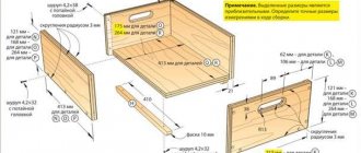
The wood splitter options shown in the photo consist of the following elements:
- frame made of metal profiles or pipes with horizontal supports;
- long boom - a lever mounted on a hinge;
- on the hinge side, the boom rests on a spring inserted between two cups;
- At the end of the lever there is a weight and a cleaver blade, plus a handle for a comfortable grip.
Note. The frame design is arbitrary. the task is to prevent the mechanism from tipping over during the process of cutting decks. Sometimes the end of the arrow is embedded in the wall or attached to various adjacent structures.
The operating principle of the wood splitter is based on enhancing the impact due to the elasticity of a manually stretched spring. Under the blade, at a convenient height, there is a stand where sawn logs are placed. The operator swings the lever with one hand like a pendulum, with the other he moves the tree under the blows of an improvised ax.
The advantages of a spring cleaver made of metal with your own hands:
- simplicity and minimal price of materials for manufacturing the device;
- the operation of the mechanism does not depend on electricity;
- thanks to the frequent vibrations of the deck lever, it is easy to chop into firewood of any size - from splinters to logs, the main thing is dexterity.
The main disadvantage of the wood splitter is the danger of putting your fingers between the oscillating blade and the block during the rearrangement process. Well, the second point: the mechanism does not relieve the homeowner from hard physical labor - you need to swing the boom, quickly move the deck and remove the firewood.
Comment. It is much more difficult to chop knotty cuttings and “slingshots” - you have to apply several blows to one point.
Electric models
Mechanized cleavers - screw and rack-and-pinion, powered by an electric motor - greatly facilitate the work of the hewer. But the cost of these wood splitters increases due to the use of motors, drive parts and special splitting tools:
- The main chopping element of the screw model is a metal cone with a large thread cut in the direction opposite to the rotation of the shaft. The spinning “carrot” itself grabs the deck with its tip, cuts into the thickness of the wood and breaks it into 2 parts.
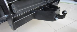
- Rack and pinion transmission is the main element of the second design with an electric drive. The principle of operation is reminiscent of a car steering rack - the block is pushed onto the stationary blade of the cleaver using a pusher attached to a toothed steel rack.
Peculiarities
Rack splitters are very reliable and efficient; they are characterized by high speed of operation and simplicity of the mechanism. The principle of operation is generally elementary - the lumps are placed on the work surface, after which the pusher is activated using a lever. It moves along the slats and with force pushes the workpiece onto a rather sharp knife, which is located at the very end of the unit.
All manipulations take a matter of seconds, and as a result the log splits into several parts.
The operating principle of such a wood splitter is based on the use of a rack and pinion gear:
- the gear rack is mobile, it is driven by a gear pressed onto the reduction gear shaft or belt drive pulley;
- the lath is fixed on the frame where the block is laid;
- the gear meshes with the rack using a special control handle;
- all these parts are mounted on a strong stationary frame, with a cleaver attached to one of its ends;
- there are guides on the frame along which the rack moves;
- With the help of a return spring, the rack returns to its original position.
The design can be driven by any type of engine - gasoline, diesel or electric; in addition, it is often driven by the power shaft of an agricultural tractor or a car wheel, that is, by any motor that produces torque. At home, some craftsmen even install a washing machine motor or a chainsaw motor.
Methods for manufacturing gears and gears
For the manufacture of gears, the following materials are used: iron, cast iron, bronze, simple carbon steel, special steel compositions with an admixture of chromium, nickel, vanadium. In addition to metals, softening materials are used: leather, fiber, paper, they soften and reduce noise. But metal gears can also operate silently if their profile is made with precision.
: Formulas and calculations
Formulas for drawing and making gear teeth can be found in abundance on the Internet, but for a beginner they seem very complicated.
I decided to simplify the problem and the solution works very well on both large and small scales. On a small scale this is best suited for machine cutting with laser cutters, for example very small gears can be successfully produced this way.
Specific problems of layer-by-layer printing
- Printed gears usually require little post-processing before use. Be prepared for wormholes and the fact that the teeth will need to be processed with a blade. Reducing the diameter of the central hole is a very common problem even on expensive printers. This is the result of many factors. This is partly due to thermal compression of the cooling plastic, and partly because the holes are designed in the form of polygons with a large number of angles that contract around the perimeter of the hole. (Always export gear STL files with a large number of segments).
Slicers also contribute because some of these programs can choose different points to go around the holes. If the inner edge of the hole draws the inner edge of the extruded plastic, then the actual diameter of the hole will have a slight shrinkage, and it may take some force to insert something into this hole later. So the slicer may quite intentionally make the holes smaller.In addition, any discrepancy between the layers or the discrepancy in the width of the intended and actual extrusion can have a quite noticeable effect by “tightening” the hole. You can combat this, for example, by modeling holes with a diameter of approximately 0.005 cm larger. For similar reasons, and to ensure that the printed gears fit next to each other and can work, it is recommended to leave a gap of approximately 0.4 mm between the teeth in the model. This is a bit of a compromise, but the printed gears won't get stuck.
- Another common problem is getting a solid fill, which is quite difficult for small gears. Gaps between small teeth are quite common, even when the slicer is set to 100% infill. Some programs deal with this relatively successfully in automatic mode, but you can manually solve this problem by increasing the overlap of layers. This problem is well documented on RichRap, and there are various solutions to it in the blog.
Apartment renovation video tutorials
Watch the best online video lessons in the apartment renovation category on our website “Video Teacher” and apply the acquired knowledge in practice. In the future, you will be able to become a jack of all trades and be able to handle all household chores without any problems. All educational video lessons are free and without registration; you can watch them at any time convenient for you. We wish you pleasant viewing and good luck in renovating your apartment.
Training video lessons on this topic will help you learn how to create and edit websites on popular engines, as well as work with their components, extensions, and plugins. Today, websites of various subjects are created using the most popular free engines such as WordPress and Joomla. Anyone who has a desire can learn a specific website engine, and video training courses and a series of video lessons on working with it can help you with this.
You will be able to familiarize yourself with the author's lessons on working with engines and hear their opinions. The authors will tell you in detail and show in the lessons how to properly configure a specific CMS to suit your needs for the successful operation of your web project. You can learn how to create your own online stores and set up virtual storefronts for your visitors for free. Today, content management systems occupy a leading position in working with websites of any complexity and focus.
WordPress
This content management system positions itself as a blog site for simple tasks. It is very popular as a job in the blogging field, creating blogs. But with a large number of plugins, this CMS has become very popular and today it is becoming multifunctional. Using the WordPress engine, multifunctional projects and online stores are created. You can learn more about how to work CMS WordPress in training video lessons and courses.
Joomla
Initially, this engine was intended for article sites. To increase functionality, you had to install additional extensions and upgrade to a new level. Now the popularity of the engine is very great and many people, learning CMS Joomla, create their own professional websites. From the lessons and courses presented on our training portal you can learn how to work with this engine.
Plywood products
Plywood is one of the most convenient materials, as it is easy to process. In addition, a sheet of plywood is much wider than any slats, so you can make a variety of products from it using a carpentry jigsaw. Here is just a small list of popular new products taken from YouTube that can be used to make cool wood crafts:
- rifled weapons of various calibers, which, although they do not fire shot, look very unusual;
- incredible wooden windmills created by gluing together only 10-15 parts;
- antique wooden carts that even a child can create;
- animals for the garden plot, cut from a piece of plywood.
Differential setting
After installing the part and cutter on the machine, it is necessary to configure the transmission between the main and secondary spindle. Different machines do this in their own way:
a) changing the guitar's idle gears
b) shifting the gearbox
c) synchronization of electric drives with frequency control.
In machines with a gear guitar, the setting comes down to representing the ratio of the module to the gear ratio, which is individual for each machine model, as the ratio of the products of numbers indicating the number of teeth in the idler gears. In modern machines, synchronization of the gear with the cutter is performed automatically in accordance with the specified processing parameters.
Required Tools
To carry out the procedure in question, a special cutting tool is required, which allows the removal of the required amount of material. The following are quite widespread:
- If the production of gears is carried out using rolling technology, then an involute gear is required, manufactured using a hard and wear-resistant material.
- The cutting of teeth using the copying method is carried out using a hob cutter. It is characterized by a certain geometry, which allows you to obtain depressions with specified parameters.
A finger modular cutter can also be installed, which is installed in special milling equipment. You can purchase modular cutters for cutting gears, made using wear-resistant materials.
Restoring a plastic gear
Restoration of teeth
We make such a peculiar tubercle.
We place the gear on an improvised stand so that the glue thickens even more. Again, everything is individual, I personally needed about 20 minutes for the consistency to noticeably thicken.
You can speed up the reaction and reduce the thickening time by heating. For example, take a hairdryer and start heating the glue on the gear.
Restoration of teeth
As a result, another gear will roll the track on the thick glue.
Now you understand that before rolling the teeth, the epoxy glue on the gear must cure to the consistency of hard plasticine. The lubrication will prevent the glue from sticking to another gear.
How to replace epoxy glue
The good thing about the above method is that it has been tested many times and is considered reliable. However, cases often arise when there is no high-quality two-component glue at hand. What can replace it with and are there any analogues?
As one option, you can use ordinary epoxy resin mixed with a special hardener. It forms quickly and is characterized by excellent flexibility, which, with the proper skill, allows you to exactly replicate the original teeth of a broken gear.
To enhance the effect, it is recommended to add dry cement to the epoxy resin, carefully prepared exactly according to the instructions, in a 2:1 ratio. By thoroughly stirring the mixture, you can obtain a composition so strong that it will help completely restore a broken plastic gear.
Now you know how to use two-component epoxy glue and its analogues to repair plastic parts. If you need help from people dealing with similar things, write about it in the comments. This way you can ask for valuable advice from those who have already repaired plastic gears and have experience in this field.
Source