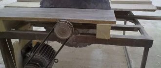
First, the base parts are cut, I did this on my circular table, then they are assembled into a frame, which is attached to the bottom of the body of the multifunctional brain table . The height of this frame should be the same as the height of the existing wheels.
#homemade #instructions #equipment_repair #inventions
Good day
to all brain crafters For those of you who do not have large workshops or small racks for tools, homemade product in this article will be useful, which compactly fits all the useful tools and can be easily moved to other work sites.
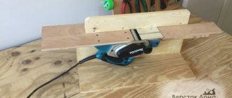
When creating this brain craft , I tried to make it as compact as possible so that it could be conveniently used even in a small space, and moved even if you don’t have a car. For this, it has transport wheels, and you can move the craft alone, and if you still use a car for this, you will only need a little help when loading. This compact homemade includes: a circular table, a milling table and a jigsaw. It also has a large cabinet in which you can store your other tools. The creation of a homemade begins with cutting all the parts and numbering them. Next, to obtain a handle slot, 4 corner holes are drilled and “finished” with a jigsaw. Then holes are drilled the same size as the diameter and thickness of the opening system washer. The holes are countersinked. After this, a place is prepared for installing the power and emergency shutdown buttons. Then, using dowels and 50mm self-tapping screws, the body of the brain table . If desired, the body parts are varnished, so the craft will look better and last longer. Having prepared the body, the 3 upper parts are assembled. To do this, parts of the folding frames are cut and the necessary holes are drilled in them. A hole for the tube is drilled of such a diameter that the tube can rotate freely in it, since it is the axis of rotation of the hinged covers. Then a cavity is selected for the circular saw. I did this using my 3D milling cutter; in the absence of something similar, this can be done with a regular milling cutter using the appropriate jigs and guides. On the front side of the circular table cover, a cavity is selected for a quick-release panel, by removing which you can change the angle of inclination of the disk. The panel itself can be used to adjust the depth of milling of the cavity. By installing the circular saw in the intended cavity, holes are marked for its fastening. A 3D milling machine is well suited for this, because these holes cannot be drilled on a drilling machine due to its limited working surface.
Step 2: Start Build
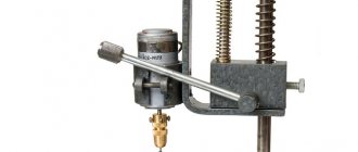
At this stage, the gradual assembly of a portable multifunctional machine for a DIY . The groove for the guide is marked and selected using a circular table. Two additional pieces of plywood will provide the necessary depth to securely attach the guide strip. Next, a strip with a self-adhesive tape measure applied to it is attached to the lid. After this, a hole is drilled for the router. Then the tubes for the rotation axes are cut off and the frames of the hinged covers are mounted on the body. In accordance with the drawings, fixing supports are made and installed. The cover of the router is applied to the frame, aligned and fastened with self-tapping screws through the holes in the guide channel. Then the cover of the jigsaw is prepared, a groove for this same jigsaw is selected in it. If a material with a non-sliding surface, such as melamine, is used for the cover, then the surface of this cover should be treated with varnish, alternating with sanding. Having done this, the parts of the vertical lifting mechanism of the router are cut out and assembled, with the help of which the depth of milling will be adjusted. Then they are glued together. two pieces of plywood to make a holder for the router itself. A hole of the same diameter, or a suitable one, is drilled into them as when creating the router cover. This holder for a milling cutter can be made on a CNC machine or even ordered online. The finished router holder is attached to a vertical lift, and now you can try it in action. To mark the radius of the tilt grooves, ordinary hinges are temporarily attached to the vertical lift, and for the manufacture of turntable handles, plywood scraps.
Step 3: Completing the Assembly
this stage of assembling the homemade product with those parts that I forgot about earlier. They will give stability to the lifting system. First, the base parts are cut, I did this on my circular table, then they are assembled into a frame, which is attached to the bottom of the body of the multifunctional brain table . The height of this frame should be the same as the height of the existing wheels. A latch is attached to the flap of one of the hinged lids, and a lock is attached to the flap of the other. This can be useful when transporting the craft and act as a preventive measure against theft of your tool. Next, prepare a 4-slot electrical extension cord, two connectors of which will include a jigsaw and a router, and the remaining two connectors will include an additional power tool. The socket for the circular saw is connected through the power button and the emergency shutdown button. The extension cord is wound around special handles made for this purpose. The quick-release panels are made of opal methacrylate. They are placed in place, and the slot in the circular saw panel is carefully made by the saw itself. I used an accessory from an old router kit as a guide bearing. This device will be useful when milling curved lines. After this, the plane of the entire upper part of the craft ; if the hinged lids do not lie in the plane of the central part, this can be easily corrected by adjusting the inclination of the fixing supports. Next, the perpendicularity of the working parts of the tools and the plane of the table is checked. To check the router, a tube is fixed in it, along which the perpendicularity of the router axis and the table plane is checked, and the parallelism of the guide channel and the circular disk is checked. And finally, the perpendicularity of the jigsaw blade is checked. After this, the table covers are folded to check whether the brain tools with each other.
Step 4: Useful Tools
This step talks about making some useful accessories for a homemade . First of all, the parts of the slide are cut, then a groove is selected for the guide slider. After this, the two plywood parts are fastened together with screws, and the positions of the screws should be chosen so that they do not interfere with the subsequent modification of this part. Then a measuring tape is glued onto it in a specially prepared groove, and this accessory for the brain table is varnished, alternating with sanding, thereby creating the necessary smooth surface on this device. The sleds are assembled, placed on a multifunctional homemade product , and the excess is cut off and a middle cut is cut, and then a measuring tape is also glued on. The guide slider is unscrewed from the sled and a groove is made for the tongue-and-groove conductor. The same as my other circular table. The channel slider is adjusted in such a way that the tilt between the bolts disappears. The slider itself can, if necessary, be stopped by simply tightening the bot to the maximum. Next, the parts for the stand are cut, it is assembled, and varnished and sanded. After assembling the rack, a fixing system for it is made. Dowels glued into this fixing system are used as axle guides. At the end of the rack assembly, the handle of the fixing system is made, and then the entire rack is checked in action. Additionally, a dust collector for the router is installed on the rack, and threaded bushings for the pressure panel are screwed into the side of the brain stand near the dust collector. Having done this, the parallelism of the rack and the circular disk is checked, then The measuring tape is glued into the groove of the side wall. Having finished this, the parts of the tongue-and-groove jig are cut, which are then glued and cleaned.
Step 5: A few more useful gadgets
This is the last video of this tutorial , and its first part shows how to make a corner stop (to create it, you can paste a printed template or use a ruler). The stop blank can already be cut on the most multifunctional machine. The thread in the guide slider is inch, but if you need a metric one, you will have to use a tap. It is definitely worth temporarily screwing the stop blank to the guide to make sure that the turning radius is made correctly. Then the parts of the tenon jig are cut, in this case, it is necessary to slightly increase the thickness of the conductor fastening to reduce friction. To make a pressure panel, a template is glued onto a plywood blank, and the adjustment grooves for this panel are selected using a milling machine . Threaded bushings are mounted in the right places on the cover with the router. Next, a jigsaw blade guide is made, the fixing system of this guide is the same as that of the stand. First, a bearing adjustment system is assembled to avoid wear of the plywood, a metal plate is used. One of the holes is made large in order to adjust the bearings through this. The same is done with plywood. After this, the height adjustment system is mechanized, and now the structure can move in three axes, thereby obtaining the required position. Finally, the finished saw guide can be checked in action, it is important to hold the sawn board with both hands so that it fits firmly enough to the plane of the table. That’s all about the compact multifunctional homemade product , good luck in your creativity! (Especially for MozgoChins #Portable-Workshop
The multi-saw machine can be additionally equipped with:
Multi-rip machines
The multi-saw machine is an easy-to-use tool that is used for cutting wooden workpieces.
Such equipment is in great demand in sawmills and other industrial plants whose activities include processing various types of wood. These machines make it possible to produce several boards simultaneously and very quickly in one pass of the workpiece through the cutting device. Multi-saw machines are designed for creating finished lumber, that is, for producing various blades, as well as for forming cuts and milling. The machines come in single-shaft and double-shaft types. Workpieces can be fed mechanically. They have high processing precision.
The main difference between this equipment and sawmills is that the sawmill does not have the same precision of operation. The design of multi-saw machines can use band or circular saws. The multi-saw disc machine has a lower cost compared to band options. However, sharpening discs is quite expensive.
Distinctive characteristics
Experts believe that peeled veneer is not the best option when using it for finishing rooms or structural elements of furniture, as well as other structures. This is due to the low decorative properties of this material.
- The veneer texture shows large gaps between the early and late layers of wood.
- Peeled is the thinnest type of veneer.
- When peeling curly wood, this type of veneer demonstrates high decorative qualities.
Curly wood is wood with a natural defect, expressed in a tortuous or random arrangement of wood fibers.
Stationary machine with your own hands
To perform everyday or one-time tasks, a hand-made circular saw is quite suitable. Small-volume sawing work does not imply heavy loads on the disk drive. The compact tool has small dimensions, which makes it possible to put it away after finishing work in a certain place. An experienced carpenter will need to make a large stationary type circular saw.
Circulation table
The main condition for making a table is the selected material. It is recommended to use a solid steel sheet, duralumin or silumin alloy. Materials such as moisture-resistant plywood, plexiglass and textolite require processing and installation on top of a galvanized sheet. The use of any material in manufacturing must meet the main conditions:
- increased vibration resistance;
- sagging with a load exceeding 50-60 kg is unacceptable;
- the presence of a perfectly flat surface.
In cases where the conditions are not met, a DIY circular saw may stop due to a jammed disk or a broken drive. The consequences can be different, from a damaged part to injury to a person.
There are several options for making a circular table. Stationary tables can be sawed or made from two parts. The circular saw blade should protrude no more than a third of its diameter.
Saw blade
Saw blade
The design of a DIY circular saw must contain a saw blade. The working surface of the disk is set to one third of the total diameter. For example, with a diameter of 210 mm, the disk should protrude 70 mm from the table. Parts with greater thickness will require a powerful motor, from 1 kW. A miniature circular saw will not cope with such tasks.
The splitting knife installed on some models serves to prevent short circuits and jamming during operation. It is located at the back a few millimeters from the teeth of the saw blade. The device may also be needed when making a circular saw with your own hands.
Adjustable side support
Any type of work will require a stop. The side support is made of a block of dense wood. In other cases, it is possible to make it from a metal corner. The arrangement should be slightly longer than the table structure. The stop is installed using bolts. The template is installed between the table and the cutter for precise installation and better settings.
Shaft
Homemade shaft
The most important part of the design is the shaft mounted on the circular saw. A self-made shaft for a circular saw can damage the structure and cause injury. The reason for this is runout, which cannot be avoided when making a shaft using artisanal methods. The manufacture of the shaft should be entrusted to a specialist with good turning equipment. You should remember that there is a cutter that needs a seat. The holes must be symmetrically machined and machined.
Finished shafts are sold in specialized markets. Preference should be given to parts with a self-aligning bearing. Otherwise, the conventional mechanism may soon render the circular machine unusable.
Broadcast
There are several types of gears that can be used in the design of a DIY circular saw:
- V-belt transmission;
- mechanism consisting of gears.
The preferred option is to use a belt drive. Using a mechanism with gears can lead to jamming if a foreign body enters and injury to the worker. When choosing the pulley diameter, the maximum number of revolutions of the saw blade is taken into account.
Motor
Electric motor for circular saw
In most cases, homemade machines are equipped with an engine from an old washing machine. The main features are increased service life and efficiency. The speed of such engines is not high, which makes working on a circular saw assembled with your own hands safer, longer, and has a positive effect on the result. The use of a special three-phase motor implies the presence of a 380 Volt network. If one is not available, you will have to use a starting and running capacitor, which leads to additional costs.
Equipment used for peeling veneer and its kinematics
Structure of a peeling machine.
Peeling is the process of cutting wood crosswise. In this case, the material being processed makes a rotational movement, and the cutting tool makes a translational movement in the direction of the axis of rotation of the material. As a result, a cylindrical piece of wood is transformed into a thin layer of certain dimensions. In this case, the cutting speed turns out to be a variable value, since the number of revolutions of the machine spindles is constant, and the diameter of the block decreases during the peeling process. This operation is performed using Fig. 85. Kinematic diagram of the LU-17 peeling machine: 1 - main electric motor; 2 - cliatic transmission; 3 - friction clutch; 4 - brake; 5 — electric motor for axial movement of the spindle; 6 - cliatic transmission; 7 - nut; S — sprocket block; 9 — clutch coupling; 10 — caliper screws; 11 — caliper; 12 — electric motor for rapid movement of the caliper; 13 - cliatic transmission; 14 — left spindle; 15 — right spindle; 16 — friction clutch engagement handle; 17 — handle for turning on the peeling feed; 18 — brake handle; 19 — handle for changing the gear ratio of the gearbox
peeling machine, the main parts of which are a frame, two spindle heads, a support, transmission mechanisms and a control system. For a more detailed acquaintance with the structure of the peeling machine and the interaction of its parts, consider the kinematic diagram of the domestic machine (Fig. 85). The block to be processed, being installed between spindles 14 and 15, is clamped by axial movement of the spindle 15. This is achieved by transmitting rotational motion from the electric motor 5 through the V-belt drive 6 to the nut 7, sitting on the threaded part of the spindle 15 and rigidly connected to the pulley dt. The possibility of axial movement of the spindle is ensured by the presence of a spline connection with the spindle nut.
The rotational movement of the machine spindles is obtained from the main electric motor l, through a V-belt transmission 2, a clutch 3 and two cylindrical helical gears with wheels z1 and z2. To quickly bring the support 11 to the block fixed between the spindles, the machine is provided with a special rapid feed mechanism, consisting of an electric motor 12 and a V-belt drive 13. Transmitting rotation to the support screws 10 through gear 13 and two pairs of bevel gears z8-z9 and z10-z11, it makes caliper 11 move.
Further movement of the caliper is carried out using a working feed mechanism connecting the right spindle 15 and caliper screws 10. This mechanism includes a chain drive with sprockets z12-z13, a spur gear z3-z4, a Norton box with zK-z5, a pair of spur gears z6 -z7 and two pairs of bevel gears z8-z9 and z10 zn.
To speed up the cylindering of blocks in the machine, it is possible to transfer motion from the spindle 15 to the support screws 10 using an independent kinematic chain, including a chain drive with sprockets zl4 - z15, a block of 8 sprockets, freely sitting on the pile III, and a chain drive with sprockets zl6 - z17 .
The machine control contains a system of levers for turning on and off the friction clutch 3 (handle 16), a hand brake for pressing the block (handle 18), a clutch control system 9 (handle 17) for turning on the working or roughing feed, as well as push-button control of electric motors 1.5 and 12. In this case, both forward and reverse buttons are provided for electric motors 5 and 12. There is also a handle 19 for rearranging the gear wheel z5 in the Norton box in order to change its gear ratio, and therefore the thickness of the veneer.
The design of the most complex and critical part of the machine - the support - is shown in Fig. 86.
The main parts of the caliper are the knife traverse e and the traverse 6 of the pressure ruler, sitting on the same shaft 15.
The knife 5 is attached to the traverse 1 using bolts 3 and lining 4. Changing its position in height is achieved by rotating the screw 2. The knife is installed at the required angle of inclination by a removable handle 14, the rotation of which changes the position of the rear part of the knife traverse.
The clamping ruler 10 (the role of which will be discussed in more detail later) is mounted on the traverse 6. Its position in relation to the knife is adjusted by the handwheel 11 and special screws not shown in the figure. When the handwheel rotates, the gear sector 13 and shaft 15 rotate. But, since the latter has eccentric journals, the clamping ruler traverse that sits freely on it will move in the horizontal direction when it rotates, which will allow the gap between the knife and the ruler to change.
The entire support is moved along the horizontal guides 16 using screws 17.
Rice. 86. Support of the peeling machine LU-17: 1 - “butter traverse; 2 - installation viit; 3 – clamping bolt; 4 — overlay; 5 - knife; 6 — traverse of the clamping ruler; 7 — installation viit ruler; 8 — clamping bolt of the ruler; 9—laying; 10 — pressure strap; 11 - flywheel; 12 - worm; 13 - toothed sector; 14 — handle; 15 — shaft with eccentric nuts; 16 — horizontal guides; 17 — running internals; 18 — inclined guides
Operating speeds of a peeling machine and their determination. The main indicator of the operation of a peeling machine is its productivity, which largely depends on the operating speeds of the machine, the value of which is established on the basis of the kinematic connections of the machine.
Based on the use of the kinematic diagram of the machine (Fig. 85), we have compiled expressions for determining its operating speeds, presented in table. 41.
Table 41. Formulas for determining machine operating speeds
Original devices
The list of homemade products can be continued endlessly, but we’d rather talk in more detail about some homemade machines that can be made from any model of drill.
Drill
A drill made from a drill is not a fantasy, but a real and fairly universal machine, assembled independently. The main thing is that you need to order from Chinese engineers (if you couldn’t find it in your city) a flexible shaft from a standard medical unit. As a result, a drill appears in your arsenal, which can be used for engraving work or drill holes using special burs in small parts or structures that cannot be reached with a standard drill.
Lathe
A woodworking or lathe for home can easily be made using a drill. The tool must be secured with special clamps quite firmly, and a specially designed holder with several sharp pins must be inserted into the chuck to keep the workpiece from turning. The center of the rear holder (headstock) and the clamp at the front of a homemade lathe should be located on the same axis. Precision is necessary to prevent runout as the workpiece rotates. After installing the part, the tailstock is firmly fixed with a special clamp.
The third element of the machine is a tool rest in the form of a wooden block on which a chisel or other tool for processing the workpiece will rest.
A lathe for processing wooden workpieces will work properly if the drill has a built-in electronic speed controller. Using the trial method, you establish the optimal rotation mode for effective wood processing. Using such a woodworking device, you can make unique products for household needs: for example, a rolling pin or pestle with a mortar, a candlestick or a prefabricated candelabra.
Winch
An original winch based on an old but powerful drill will become an indispensable assistant in the household, especially for those users who live in their own home and have a personal plot. A simple situation: you decided to install a larger container in your summer shower, but raising it to such a height alone is problematic. Using a winch, this can be done in a few minutes. You just need to first calculate the weight of the container and the spindle speed.
According to garage craftsmen, a homemade winch can easily lift the engine from a passenger car. Watch the video if you don't take my word for it:
Experts advise using a homemade device, setting the drill at the lowest speed. This design can move objects with different masses, because craftsmen even make winches based on an ordinary car starter.
Electrical part
It is better to do the electrical wiring from a familiar technician, or contact a professional electrician, than to do it yourself. Often it is the wiring that fails at the most inopportune moment. It is worth noting that, as a rule, when working with wood, piles of sawdust are formed around the machine, which are easily flammable, so it is better to entrust the power supply to the machine to a professional.
Installing the working area on the frame with your own hands does not require any special skills. The hardest part is: marking the cuts. To do this, take cardboard according to the size of your future desktop, cut out an oblong hole in the place where it rests on the cutting element. The hole is located in such a way that when rotating the disk does not scratch the cardboard and is at least 3 mm from the edge of the workpiece. We retreat to the right side 5 mm, and draw a perpendicular line and outline a contour 7 mm thick around it. Thus, we designate the adjustment slot of the guide die.
Special protection for hands
Having cut out a strip of 5 mm metal, the width of the working plane, and a height of 50 mm, we weld two bolts with a diameter of 12 mm symmetrically to the center. With these bolts we will regulate the movement and displacement of the thrust guide bar of the working surface.
We cut out all the necessary slots using the cardboard blank, install the guide die and weld it directly to the frame.
After installing all the equipment, you need to connect the sawing machine to the network with your own hands and check the correct rotation of the circle. The circle should rotate clockwise (towards the board).
It is best to make the first start remotely using a long carry and a circuit breaker.
After checking, it is necessary to test the power capabilities of the unit. There are several ways to do this.
Production Features
The technology for manufacturing peeled veneer has been known since the beginning of the 19th century, and over the years, the equipment used for the production of veneer has undergone many design changes and technical changes. However, the basic principles remain unchanged.
Churak, or in other words, the workpiece, which has previously been dried, is fed to a special peeling machine. The size of the block, length and diameter, depend on the model of the machine and its technical characteristics.
When the workpiece is fed to the machine, it is fixed in spindles, devices installed at the ends of the block.
An important point when installing a workpiece is correct alignment, because otherwise, during the next operation, rounding, there will be a large percentage of wood waste.
Rounding is a technological operation when, when rotating a block, sections of wood and its unevenness are removed from its surface. Removal is carried out until the workpiece is given the appearance of a correct cylinder.
After the cylinder is formed, the peeling process begins.
In this mode, simultaneously with the rotation of the block, the cutting knife moves in the direction of the center of rotation, which leads to cutting off a layer of wood of the required thickness.
The cut wood sheet (veneer) is wound on a special device (reel), located next to the peeling machine, or cut to the required size.
Distinctive features of the production of peeled veneer on an industrial scale are:
- the need to prepare blanks used for the production of veneer (hydrothermal treatment, heat treatment);
- sorting workpieces by diameter and length (crosscutting);
- sorting of assortments by types of raw materials and quality.
Purpose of multi-rip machines
The functions of the machines are very different. They can produce boards from a two- and three-edged carriage, cut timber into smaller boards, produce a board from a slab, then the saws in the machine are not only longitudinal, but also transverse.
Most people use a multi-saw after cutting the log down to a two-edge beam with a band sawmill. Models differ in the number of saws, band or disk. The maximum number of installed disks is 24 pieces.
When choosing, take into account the power and weight of the unit. Large productive machines can weigh more than one ton, and a concrete foundation will be needed so that the tool stands level and does not vibrate during operation.
Traditionally, wood sawing machines have a single saw blade. If the operation of cutting material into pieces of equal width is performed many times a day, you should think about buying a multi-saw. It has better performance.
Flaws
The choice of one or another type of veneer is influenced by the presence of disadvantages inherent in each of the materials being compared.
Thus, peeled veneer has the following disadvantages:
- large losses of wood associated with the preparation (rounding) of blanks;
- the veneer texture has an uneven and non-repeating structure with wide veins;
- the right side of the veneer turns out to be uneven and torn, which is due to the production technology.
Veneer peeling is a technology that makes it possible to produce various types of building materials at low cost for various types of construction and installation work.
| Lumber for construction: making chipboard, making fiberboard, how to make joinery boards, plywood, veneer) |
Peeled veneer - what is it?
Veneer is a building material consisting of flat, thin sheets of wood of varying thicknesses.
Depending on the equipment used and production technology, veneer is produced with a thickness of 0.1 - 10.0 mm, and in accordance with the production method, it is classified as: sawn, planed and peeled.
Peeled veneer is produced on special equipment, peeling machines, the principle of which is based on cutting layers of wood of a given thickness from a cylindrical blank rotating around its axis.
Various tree species are used to produce peeled veneer: birch, aspen, alder, beech, maple, linden, poplar, spruce, pine, larch, fir and cedar. It is used for the production of plywood and other board building materials (carpentry, plywood boards, etc.), for the manufacture and cladding of furniture.
Depending on the quality of the wood used, its species, as well as the quality of processing, depending on the type of equipment used, peeled veneer is divided into five grades, these are:
- E (elite), I, II, III, IV – for hardwood;
- Ex (elite), Iх, IIх, IIIx, IVx – for coniferous trees.
The document regulating the production of peeled veneer is GOST 99-96 “Rolled veneer. Technical conditions".
Currently, a new document has been developed, in accordance with which this building material will be produced in the near future, this is the Interstate standard “GOST 99-2016 Peeled veneer. Technical conditions”, which is currently being approved by regulatory organizations.
Machine design
All of these devices have certain basic parts:
- Bed - includes all components of the device, may also include a lumber supply line.
- Power unit - creates a rotational or reciprocating motion of the saws processing the material. It also drives the workpiece feed unit.
- Sawing mechanism - consists of one or more shafts on which saw blades are installed. The shafts can be in a horizontal or vertical plane.
- The mechanism responsible for feeding the workpiece. The larger the feedstock, the more powerful this unit should be. It is responsible for uniform transportation of the carriage or timber. The accuracy and evenness of the saw depends on this element.
What technology is used to produce fine-line veneer?
Fine-line veneer is a new modern material that imitates various types of wood. Today it is often used in decorative finishing of cabinet furniture and door panels when it is necessary to create interiors “like wood”.
To make fine-line veneer, in most cases, inexpensive raw materials are used, which are subsequently artificially colored to give the material an external resemblance to more valuable tree species. In addition to the shades of natural wood of expensive varieties, this material can be painted in other artistic colors.
Fast-growing tree species are used as raw materials for the production of fine-line veneer. The process consists of peeling logs to a given thickness, followed by cutting the resulting strips to the desired size. Then the blanks are dried and sorted by color. After this, the sheets are painted and, using a press, glued into blocks, which are planed, resulting in a material with an unusual texture.
Among the advantages that distinguish this material from natural material is the absence of characteristic defects. However, some may regard this as a minus, since it is thanks to natural flaws that natural wood is so unique and valuable.
This type of material is environmentally friendly. Although it looks like plastic in appearance, it is a natural material.
In addition, fine-line veneer is resistant to temperature changes; they do not in any way affect its properties and appearance. The material is not afraid of high humidity; it will not deteriorate even in the event of direct contact with water.
Technical specifications
Among the main technical parameters of multi-rip machines, it is worth highlighting:
- workpiece sizes. The maximum size of raw materials that can be processed determines the permissible dimensions of the workpieces
- number of installed saws. This parameter shows the largest amount of timber per run
- Feed speed affects the productivity level of the machine
- workpiece cutting speed
- saw diameter characterizes the depth of cut
- the largest distance between the saws is responsible for the width of the final timber
- power indicator
- dimensions of the equipment itself
- weight.
Taking these parameters into account will help you select a machine for the volume of work you need, operating conditions and production purposes.
Multi-saw machine design
Regardless of the type, this equipment has a stable and heavy frame that holds all the elements of the device and the workpiece feeding mechanism, a power unit responsible for creating rotational or reciprocating forces, and shafts with saws fixed in a horizontal or vertical plane. Accordingly, the larger and denser the initial raw material, the more powerful the components of the machine and its engines should be; models are powered primarily from a three-phase network.
The most functional varieties have the ability to adjust the width of the stand (the distance between the saws), are equipped with CNC units or control the material feed speed. The latter allows you to process wood blanks with different densities and dryness with the same precision; the smoother this characteristic changes, the better. Budget multi-rip machines do not have this option or do it in stages.
Features of operation
Despite their unpretentiousness, multi-rip machines require compliance with certain maintenance rules; in order to reduce defects and extend their service life, it is recommended:
- It is recommended to control the feeding speed of workpieces or logs depending on the material parameters and loads; it is recommended to feed denser and greener wood slowly.
- Adjust the machine when defects appear, monitor the sharpness of saw sharpening and promptly change cracked or worn out tools.
- Clean equipment from chips and dust after work.
- Lubricate working units at the intervals specified in the instructions for the unit, and comply with other manual requirements.
- Carry out systematic equipment diagnostics. The feed line requires special attention; its rollers or rollers must be in perfect condition; deviation can lead to a violation of the geometric accuracy of the parts produced by the machine and failure of the entire line.
Spindleless peeling. What's new?
The peeling machine was invented at the end of the 19th century. Without this equipment today it is simply impossible to imagine the production of plywood and the manufacture of matches. Over the past hundred-plus years, many designs and modifications of machines have been created, but the principle has remained the same: cutting a thin strip of wood from short logs.
But with many advantages, traditional peeling machines also have serious design disadvantages associated with the need to use cams that stick into the ends of the blocks and force them to rotate. Often the block turns in the fists and further peeling becomes impossible. As a rule, this occurs due to heart rot, which is especially common in aspen logs. As a result, the so-called screws are obtained - blocks of large diameter, unsuitable for further processing on a peeling machine.
Another disadvantage of the traditional peeling technique is the loss of wood in the form of peeling residues, the so-called pencils. The diameter of the “pencil” depends on the diameter of the internal cams of the machine and the length of the block. With a block length of 1.6 m, the diameter of the “pencil” is usually 75 mm, and with a length of 2.5 m – up to 100 mm. Wood losses account for 10–12% of the block volume.
The desire to get rid of these shortcomings led equipment designers to the idea of a spindleless peeling machine. For the first time, this idea was probably implemented by the company Raute (Finland) back in the 1990s (Fig. 1) in machines for peeling logs with a maximum diameter of 400 mm and a length of 1.7 and 2.8 m.
The rotation of the blocks in the machine was carried out by drive grooved rollers located at an angle of 120° to each other. The upper roller simultaneously served as a pressure ruler, and the lower ones moved linearly as the diameter of the block decreased. Each roller is equipped with an individual hydraulic drive. During the peeling process, the knife support was slightly rotated relative to the block, which ensured optimal parameters for peeling the block up to a pencil diameter of 50 mm. The position of the shafts, veneer thickness and cutting angle were controlled by a microcomputer. The diameter of the block was measured before it was fed into the machine to determine the clearance between the shafts.
For some reason, the technology of spindleless veneer peeling has not been developed in Europe, but has become widespread in Asian countries. In Southeast Asia, many enterprises use spindleless peeling of fine raw materials and peeling of pencils. Typically, a peeling line consists of a debarking machine, a spindleless peeling machine with rotary shears.
In the debarking and rounding machine, the block is clamped by three drive toothed rollers and driven into rotation. A knife, similar to a peeling knife, removes bark and irregularities and gives the block a cylindrical shape. The initial diameter of the block is up to 500 mm, after rounding it is no more than 360 mm.
The transfer conveyor levels the logs and feeds them to a spindleless peeling machine equipped with three finely knurled drive rollers and a peeling knife. The maximum diameter of the block is 360 mm. The diameter of the pencil is 30–40 mm depending on the machine model. The thickness of the resulting veneer is from 1.0 to 3.0 mm. Linear peeling speed – 40 m/min. After peeling, the veneer is sent to rotary shears, where it is automatically cut into formatted sheets.
The technology for peeling thin-dimensional logs will be of interest to Russian enterprises that have to work in our difficult conditions. Chinese peeling machines also operate in Russia, for example, at a plywood mill in the town of Suslonger in the Mari El Republic, at the Ufa plywood-board plant, and near Nizhny Novgorod.
The latest offering from Weihai Hanvy from China is the HVPL1326 line with a debarking machine and a spindleless peeling machine with Siemens HXQ2700 CNC and electronics from Scheider. The new spindleless peeling machine is designed for processing logs with a length of 2.6 m and a maximum diameter of 500 mm. Pencil diameter – 40 mm, peeling speed – 40–100 m/min. The machine provides for changing the angle of the knife during peeling, pneumatic fastening of the tool and automatic adjustment of the veneer thickness.
Raute did not abandon the idea of creating a spindleless peeling machine and developed the RD1400, RD1700 (Fig. 3) and RD2800 lines, each of which contains four units with the necessary transport connections: a debarking machine, a peeling machine, rotary shears and a vacuum veneer stacker ( Fig. 2).
Raw materials (blocks of a given length) are fed to a transverse conveyor with dosing stops. During the process of debarking and rounding, the logs acquire the cylindrical shape necessary for peeling and are transferred to the peeling machine using another transverse conveyor.
The kinematic design of the machine has undergone fundamental changes in comparison with previous models. The churak is fed into the machine from above, then pressed against two finely grooved drive rollers, which are mounted on a single support. In a debarking machine, the feed of the roller support is hydraulic, and in a peeling machine it is electromechanical. The third roller is located on a stationary support with a peeling knife and plays the role of a pressure ruler (Fig. 4).
The churak in the machine is self-centered at three points. When the roller support is fed forward, the block is pressed against the knife support, and the veneer is peeled. The thickness of the veneer is set from the control panel by setting the gap between the knife and the pressure roller; during peeling, the cutting angle automatically changes to ensure optimal peeling parameters (Fig. 5).
Rotary shears for cutting veneer are installed in the chain behind the peeling machine. They cut the leading edge of the veneer strip, separating the format veneer from the waste. The leading edge of the veneer sheet is detected using photocells. Next, the passage of veneer along the chain is controlled using a pulse encoder. Chopping is performed by rotating the knife located above the lower rubber roller. There are three knives installed on the knife shaft. An autonomous sensor recognition system controls the start and stop of veneer cutting.
DIY sawmill with a gasoline engine
In the process of choosing equipment intended for wood processing, it is also necessary to take into account the high cost of the tool itself. It is for this reason that few consumers can afford to buy a sawmill. But as we said earlier, anyone can make this kind of tool themselves.
Homemade sawmill with a gasoline engine
At this point you can learn how to make homemade circular sawmills with your own hands with a gasoline engine. We will also take a look at a homemade circular sawmill driven by a PTO. So, let's begin to consider this issue.
First of all, what you should stock up on is patience and a great desire to acquire this kind of device.
In order to actually begin this process, first prepare drawings for a homemade circular sawmill (can be obtained on the Internet), and also prepare construction sawhorses, metal plates, boards, screws, screws, nuts, a special tool with the use of which you can work with wood and metal, as well as the gasoline engine itself. So, let's get started.
- First, you need to obtain all the necessary information regarding the device of this tool itself, in order to have the opportunity and understanding of what and how you should produce.
- In addition, there is another option, which has the saw itself mounted on the motor shaft. On the very surface of the sawmill, processing of the so-called sawlog begins, which actually divides the unedged board. You also need to cut special blanks, each of which must meet the required size.
- It is worth noting that the simplest design of this process is the table. It is under its lower part that you must actually place the shaft itself with the saw mounted on it. The cutting part with which it is equipped should rise, so to speak, on the table surface itself. the movement of the saw shaft is produced by the action of a gasoline engine on it, which transmits peculiar impulses to the belt itself.
- Actually, the discs themselves for this kind of sawmill will serve best if they are made of duralumin or steel sheets. And its actual size should correspond to three millimeters. And the actual diameter should be 500 mm. It is important that if you are making a device in order to subsequently cut wood, then in this case you will need a disc with two or three teeth. Since this is the best option for this type of work.
- It is worth noting that the basis for the high level of sawmill production is the very manufacture of these teeth. In addition, the most important thing is that you carefully carry out the balancing and determine the correct cutting angle.
In the video you can watch how to do this:
How to make a sawmill with your own hands
Wood remains the favorite material in construction, in the manufacture of utensils for the home and household, as well as a wide variety of decorative items, furniture, etc., just as hundreds of years ago.
And the owner, who has the skills to work with equipment and skilled hands, can make a sawmill with his own hands. This will allow him to be able to prepare boards and other lumber on site according to his own needs, the desired size and type, and it will cost much less than purchasing finished products. Especially relevant when it is necessary to process a large number of boards and other lumber. Although it is generally accepted that the best option would be to purchase a ready-made machine, making it yourself is also possible and affordable if you have the desire and minimal working skills. Based on this, it is worth understanding the question of how to make the sawmill on their own, so that it is reliable, convenient, safe and meets the requirements in this particular case.
A little about the issue in general
When setting yourself the task of making a sawmill with your own hands, you should first of all decide on the volume of work for which this unit is planned to be used, as well as the type and geometry of wood (raw materials). Based on these parameters, you can already choose the type of sawmill that is best suited for solving the tasks at hand. Maximum attention when designing and manufacturing a mini-sawmill should be paid to safety - any equipment of this class is high-risk equipment and requires a very careful attitude. The presence of a sawmill is invaluable in in the household of a craftsman who often works with wood, because it will help solve such non-trivial issues for manual work as:
- produce a significant number of products of the same size and shape;
- sawing logs according to a predetermined pattern.
In industrial sawmills, logs are processed according to two standard schemes:
- Sawing a stationary log with a cutting element mounted on a mobile trolley;
- The log is pushed (or pulled) along rollers or rollers through a stationary cutting block.
When making a sawmill yourself, both of these schemes are used, and its specific type is selected depending on the design planned for assembly. If we talk about the types of sawmills, the main ones are corner, strip, and chain. Additionally, when it comes to homemade units, it is worth highlighting devices using a chainsaw as a base. Each of the listed types has a number of features and design differences from others, and therefore requires separate consideration.
Band sawmill
The general principle of operation of a band sawmill is that a trolley with a band saw blade moves along a log rigidly fixed on a stationary platform, cutting it. The location of the sawing part of the band is horizontal, and the band itself is well tensioned. By adjusting the height of the band saw, the size (thickness) of the sawn part of the log (board, beam, etc.) is calibrated. Such a device can usually work with logs weighing up to 300 kg. Assembling a sawmill of this type on your own is quite difficult, since achieving coherence in the operation of all structural elements, the task is difficult to achieve. In addition, to install the structure, it is necessary to select special components, tools and devices, and draw up fairly complex drawings, taking into account all structural elements.
Assembling the complex must begin by preparing a flat area of suitable size and compacting its surface (if it does not have a hard surface). The next stage of work will be the assembly of the frame of the unit, which should begin with the manufacture and installation of rails for the trolley. You can use a corner with the shelf facing up as a rail.
Sleepers from a pipe, channel or angle are welded between two rails to securely fasten them to each other. A mobile fastener for logs is attached to the sleepers, which must securely fasten wood of any diameter (within the limits planned for processing). Now it is necessary, according to the prepared drawing, to assemble and install a mobile cart on the rails and check its progress along the entire length of the working area. The circuit will also require wheels (you can use assembled automobile wheels, along with tubes and tires), which are used to tension the band saw. Their installation on the frame is the next stage of installation.
All that remains is to mount the electric motor, connect it via a pulley to the mechanism of the unit and check the operation by starting it.
After checking the operation of the mechanisms and parts, you can install the tension band of the saw, make adjustments and test run the sawmill.
Chain type installation
The do-it-yourself bus sawmill, in its operating principle, is very similar to a band saw, but as a cutting element it uses not a band saw, but a chain saw. However, it should be noted that its design is much simpler, the installation itself is smaller in size, and fewer quantities are used. requiring significant adjustment of parts - this together makes the bus mini-sawmill easier to independently manufacture and use than a strip sawmill. The beginning of the manufacturing process also begins with the preparation of the working site on which the metal frame of the future sawmill is installed in such a way as to ensure easy access to it from any sides.
A frame is assembled from profiled metal, in which technological holes are drilled (the number will depend on the required step). Now you need to mount the frame with stiffeners.
As a result, the base of the machine is assembled. A movable cart is assembled on the frame, installing stops, gaskets, clamps and an electric motor. After checking the functionality of all parts and structural elements, you can install and tension the saw chain and make a test cut, make adjustments and get to work.
Mini sawmill corner disc
A self-made angular circular sawing unit is very useful in a home workshop for processing wood into various types of lumber. Perhaps this is the most versatile and powerful mini sawmill - you won’t be able to make a more complex structure with your own hands. After preparing the drawings and purchasing all the necessary components and structural elements, you need to prepare, as in previous cases, the site for installation. A frame base is assembled on it, the material for which is metal pipes and high-strength guides (the design involves heavy loads and the material must correspond to them). Guides for a mobile platform should ideally be made of rails, again due to increased loads. The next stage of assembling the carriage should be characterized by increased attention to maximum compliance with the dimensions according to the drawing.
It is recommended to use a high-power internal combustion engine (ICE) as a drive - this will increase the efficiency of sawing large quantities of raw materials and simplify working with dense wood varieties.
It is best to use a chain to transmit torque, although if the design is not well thought out, this can lead to increased heating of the transmission mechanism. For safety reasons, all moving parts of the drive must be enclosed or protected by a casing.
Chainsaw as a basis for a sawmill
Most craftsmen who work a lot with wood have a chainsaw. Thanks to its availability, low cost and simplicity, it is quite easy to make a sawmill from a chainsaw with your own hands. There are quite a lot of options for a mini-sawmill, the main element of which is a gasoline saw, but all of them It is distinguished by its simplicity, small size, and mobility (it can be easily moved from place to place). To make a sawmill from a chainsaw, you will need the following components:
- channel;
- metal corners;
- rails;
- chainsaw as the main element.
At a place prepared for work, which needs to be leveled if necessary, a frame is assembled with holes for fasteners and ties made of metal pipes. Fastening is done using bolts. It is necessary to constantly monitor the angular dimensions to ensure that exact perpendiculars (right angles) are maintained. Additional stiffening ribs should be provided in the design, which will strengthen the structure. The basis for the mobile platform is a metal plate with two corners welded on the bottom side. This base is mounted on rollers (preferably bearings). On the top of the plate there should be corners welded to which the chainsaw will be attached. The last stage is the installation of the structure to securely fasten the log when cutting it.
As practice shows, if you have not too much skill, making a sawmill with your own hands is not particularly difficult. The main thing is attentiveness, strict adherence to the data indicated in the drawing and “straight hands”. During operation, it is also necessary to observe safety measures, since this type of equipment is high-risk.
Immediately after the first tests, it is recommended to make a canopy over the working platform to prevent atmospheric moisture from entering the electric motor winding or control unit.
Making a homemade sawmill
Before manufacturing the installation, detailed drawings of all components included in the design of the unit should be drawn. The simplest installation option is a single-disc sawmill. The scheme of such a design includes the following elements:
- moving carriage;
- two electric drives.
One of the electric drives ensures the movement of the portal along the guides, and the second drive serves to move the circular saw.
Sawmill assembly diagram.
This design is called horizontal. The device carriage is made of metal; it should easily move on rollers along the installation guides.
Making equipment with your own hands begins with preparing tools and materials for construction, these are:
- construction trestles;
- boards;
- metal plates;
- elements;
- electric motors;
- a set of tools and accessories for assembling the unit.
To manufacture the unit, you first need to assemble the frame of the device. For this purpose, construction trestles are combined using boards. The length of the boards used depends on the size of the material that is supposed to be processed on a homemade machine.
After making the frame, proceed to the plane of the table. Its base is made of wood, and metal plates with a width of 230-250 mm and a thickness of 1.2 mm are fixed to the surface. The plates are connected to each other by jumpers and screws. After making the table, a groove is made in its wooden part in such a way that the installed circular saw does not come into contact with its edges.
You can make a cutting tool yourself, but it is best to purchase it at a hardware store. The disk is fixed on a shaft, the drive of which is carried out using a belt drive. When securing the engine, it should be possible to move it slightly, which is necessary to tension the belt drive. The guide for the sawmill is made of boards.
Pereosnastka.ru
Design of peeling machines
TO
category:
Production of plywood
Design of peeling machines
Peeling machines are divided according to technical indicators: - according to the greatest distance between the centers of the spindles. This distance determines the maximum possible length of the knife and the length of the logs to be peeled.
The most common are machines for peeling logs with lengths of 1350, 1650, 1950 mm. The length of the block is determined by the size of the veneer sheets;
- according to the height of the centers of the spindles above the bed.
The height of the centers is determined by the largest radius of the block with an allowance of 100-150 mm.
Domestic machines are designed for peeling raw materials with a diameter of 60-70 cm. Foreign companies produce machines for peeling logs with a diameter of more than 80 cm.
The LU-17-4 peeling machine consists of the following main parts: a frame, two spindle heads, a kinematic unit support, a pressing mechanism, and a centering and loading device.
The machine bed is used to fasten all the main parts of the machine, to absorb dynamic cutting loads and auxiliary peeling operations.
The bed is a rigid welded frame made of I-beams, on which cast-iron spindle heads are installed. There is a slot in the frame for throwing the pencil down onto the conveyor.
The spindle headstocks (right and left) serve to secure the block and give it rotational movement.
In Fig. Figure 2 shows a section of the right spindle head. The spindle head has two telescopic spindles with corresponding cams.
The presence of a large cam allows you to avoid splitting of blocks during the initial period of peeling, and a small cam makes it possible to peel a pencil with a diameter of up to 70 mm.
Clamp the block on the machine as follows.
Rice. 1. Machine LU-17-4: 1 - bed, 2 - left spindle headstock, 3 - centering and loading device, 4 - welded beam, 5 - pressure rollers, 6 - right spindle headstock, 7 - block clamping mechanism, 8 - hydraulic drive, 9 - hollow shaft, 10 - cast iron beam, 11 - caliper, 12 - drive for accelerated movement of the caliper, 13 - electric motor, 14 - block feeding mechanism
The pump supplies oil from the hydraulic system to the distributor. The piston under pressure moves the rod in a large hydraulic cylinder up to 150 mm.
The piston rod, rigidly connected to the movable bearing assembly of the small spindle, also moves along the length of the hydraulic cylinder. The small spindle is secured to the small spindle bearing assembly.
The latter, moving freely inside the hollow large spindle, clamps the block with its cam.
Rice. 2.
Section of the right spindle head of the LU-17-4 machine: 1 - piston, 2 - large hydraulic cylinder, 3 - piston rod, 4 - movable bearing assembly of the small spindle, 5 - housing, 6 - spline bushing, 7 - gear key, 8 - gear, 9 - sprocket key, 10 - sprocket, 11 - rotor, 12 - hollow large spindle, 13 - small cam, 14 - large cam, 15 - small spindle, 16 - spherical roller bearings, 17 - splined bushing of the large spindle, 18 - lever, 19 - movable bearing assembly of the large spindle, 20 - splines, 21 - key, 22 - sliding keys, 23 - small hydraulic cylinder, 24 - small piston with rod, 25 - pin
Oil simultaneously enters the large and small hydraulic cylinders. The small piston with the rod moves towards the block and, acting on the lever, displaces the movable bearing assembly of the large spindle.
The amount of displacement of the small piston with the rod depends on the size of the small hydraulic cylinder and is 150 mm.
A hollow large spindle fixed in a movable bearing assembly moves by a specified amount and clamps the block with a large cam.
Thus, two spindles simultaneously clamp the block with cams attached to them. The operation of the left spindle is similar to that of the right one.
After clamping, the block is given a rotational movement from the main shaft through the gear. The rotating gear, through a key, rotates the sleeve, which, with the help of a splined sleeve 6, rotates the large hollow spindle. The large spindle rotates the small spindle through the spline bushing of the large spindle.
Sliding keys protect movable bearing units from rotation; at the same time they act as guides for the horizontal movement of these units.
During the peeling process, when the peeling knife approaches the rotating cam of the large spindle, the hydraulic system returns the large spindle to the starting position. The same thing happens when the peeling knife approaches the cams of the small spindle.
The system for supplying oil to the hydraulic cylinders to return the spindles to their original position was shown in Fig. 1.
The hydraulic system is connected to the spindle heads in such a way that when oil is supplied to the pistons of the large and small hydraulic cylinders, these pistons return to their original position. Thanks to the hollow design of the large spindle and the spline connection of the two spindles, their independent movement relative to each other in the horizontal plane is achieved.
Thanks to the use of spindle heads, it became possible to peel blocks with a diameter of up to 70 mm on the LU-17-4 machine, abandoning the use of small peeling machines for this operation.
The support of the peeling machine is designed to secure the knife, adjust it, configure it, and to give it a reciprocating movement (to the block and back).
The support consists of two side sliders moving along horizontal removable parallels located on the machine bed; knife traverse - for attaching and adjusting the peeling knife; crossbars of the clamping ruler - for fastening and adjusting the clamping ruler of the machine; two caliper screws that impart reciprocating movement to the caliper.
The support has additional upper and lower guides, with which the knife traverse is connected and with the help of which the cutting angle is changed during peeling of logs. The pressure ruler is connected to the knife crossbar by an eccentric shaft.
The block pressing mechanism eliminates the deflection of the block at the end of peeling under the influence of cutting forces.
This mechanism consists of a cast iron beam mounted on a hollow shaft, two pairs of pressure rollers, a hydraulic cylinder for moving the rollers mounted on a welded steel beam connecting both headstocks of the machine, as well as a device for adjusting the synchronization of the movement of the knife and pressure rollers. The pressure roller block is pivotally connected to the beam and to the hydraulic cylinder rod. The journals of the hollow shaft are installed in bearings, the housings of which are attached to the headstocks of the machine.
The kinematic unit of the machine serves to connect the working parts of the machine (support and spindle heads) and give them working movements.
In Fig. Figure 3 shows a kinematic diagram of the LU-17-4 peeling machine. A block centered and clamped in the spindles of the machine (the operation of the centering and loading device will be described below) is driven into rotation from the main shaft through gears. The main shaft is connected to the electric motor through a V-belt drive and an electromagnetic clutch.
Rice. 3.
Kinematic diagram of the LU-17-4 peeling machine: 1 - main electric motor, 2 and 22 - V-belt drive, 3 - electromagnetic clutch, 4, 5, 6 - gears, 7 - main shaft, 8, 9, 10, 16, 17, 18 - sprockets, 11 - intermediate shaft, 12 - right hollow shaft, 13 - cam clutch, 14 - transmission shaft, 15 - left hollow shaft, 19, 20 - bevel gears, 21 - support shaft, 23 - electric motor for rapid approach and retraction calipers, 24 — caliper screws, 25 — pistons of the hydraulic cylinder of the servo system, 26 — pneumatic cylinders for centering the blocks, 27 — feed mechanism for the blocks, 28 — handle for switching the accelerated and working feed of the caliper, 29 — electromagnet; a, b, c, d - replaceable gears for dialing veneer thicknesses
The left spindle is driven into rotation from the main shaft also through gears. The gear, rotating the sleeve of the right spindle, imparts rotation to the sprocket. The sprocket is connected to the intermediate shaft by a bushing-roller chain through a sprocket rigidly fixed to the intermediate shaft.
The shaft drives the right hollow shaft into rotation through replaceable gears a, b, c and d. Through a cam clutch mounted on a sliding key, rotation from the hollow shaft is transmitted to the transmission shaft.
Through a sprocket rigidly fixed to the shaft and a bushing-roller chain, rotation is transmitted to the support shaft through the sprocket.
A system of bevel gears drives the caliper screws, and the latter drives the caliper, which moves along guides to the rotating block. The translational movement of the caliper is carried out thanks to caliper nuts, rigidly connected to the caliper body.
The amount of caliper feed per block revolution, i.e.
the thickness of the removed veneer depends on the location of replaceable gears a, b, c and d, since a rigid connection in all links of the kinematic circuit, except for replaceable gears a, b, c and d, ensures a constant gear ratio.
The table shows that changing the veneer thickness from 0.2 to 3.2 mm is achieved mainly by changing gear a with the mutual arrangement of the block gears (b - c) in two positions.
Towards the end of peeling, when the diameter of the block approaches the diameter of the small cam of the spindle, the working feed of the caliper stops when the claw clutch is moved to the neutral position with the handle. At the same time, the electromagnetic clutch is removed from the connection with the V-belt pulley and the rotation of the pencil in the machine spindles stops.
Using an electromagnetic clutch, you can stop the movement of the main shaft without turning off the main electric motor, which is economically feasible, since starting torques when turning on the electric motor negatively affect the power supply of the enterprise.
The hydraulic system returns the spindles to their original position, and the pencil is removed from the workshop through a slot in the frame by a conveyor.
By rotating the caliper shaft in the opposite direction relative to the working movement of the electric motor, the caliper is returned to its original position through a V-belt drive.
The caliper is fed to its original position at an accelerated feed, which gives a significant gain in time. After this, the electric motor is turned off. In this position, the peeling machine is ready for peeling the next block.
Then the operation is repeated as described above.
In addition to the working feed, which ensures the production of veneer of a given thickness, the peeling machine has an accelerated feed, which is used in the initial period of peeling to remove large irregularities on the block.
The rapid feed is activated by the left hollow shaft coupling. The rotation of the shaft is transmitted to the shaft through the coupling. Further rotation is transmitted as during working feed. The rotation of shaft 15 is carried out from the shaft by sprockets and a bushing-roller chain.
In this case, the system of replaceable gears a, b, c ig is disabled and does not take part in the work.
After finishing the stripping (at the accelerated feed of the caliper), move the claw coupling with the handle, thereby turning off the shaft and turning on the shaft. Next comes the peeling process at the working feed. The electromagnet serves to automatically move the dog clutch to the neutral position.
Rice. 4. Diagram of the centering and loading device: 1 - freely rotating axis, 2 - pneumatic cylinder, 3 - lever, 4 - load, 5 - upper gear, 6 - sector without teeth, 7 - pincer grips, 8 - two-way valve, 9 - lower gear, 10 - gear sectors
The centering and loading device is used for correct centering of the block, i.e., reducing the loss of veneer during the peeling process, and for loading the block into the peeling machine.
As a rule, centering and loading devices of the system of A. Zhukov, V. P. Banko and A. A. Porokhin are installed on peeling machines. Thanks to this device, it became possible to simultaneously center the block and feed it to the spindles of the peeling machine.
The centering and loading device consists of two pneumatic cylinders that rotate freely on axes attached to the frame of the peeling machine. The protruding hubs of the lower gears are equipped with levers with split clamps, which allows the levers to be mounted on the hub in any position. The levers are pivotally connected to the piston rods of the pneumatic cylinders.
Lifting and centering of the block is carried out by turning the handle of a two-way crane. In this case, compressed air enters the pneumatic cylinders. When the pistons rise, the rods turn the levers, which, with the help of gears and gear sectors, bring the pincer grips until they come into contact with the surface of the block.
When clamping the block with spindles, its axial movement occurs. The unevenness of the block can slightly spread the jaws of the pincer grips due to air compression in the cylinders, without creating additional forces in the mechanism links.
The compression speed of the pincer grips is regulated by the degree of opening of the air valve.
The opening of pincer grips is carried out under the action of weights attached to the ends of the levers, or by springs, as shown in Fig. 19. Turn the handle of the two-way valve to open the air outlet hole.
The device operates at a network pressure of 4-4.5 ati. The air consumption per peeling machine is 0.7 m3/h. The upper and lower pliers are secured to the shafts using through parallel keys in the appropriate positions relative to the gear sectors.
Regulation of the relative position of the upper and lower pincers, ensuring the symmetry of their movement (on which the accuracy of centering depends), is carried out using a special device.
The upper sectors of this device are double. The sector without teeth is rigidly attached to the axis of the upper claw, and the gear sector sits freely on the axis and is connected to the upper gear.
It can move relative to the sector and be rigidly attached to it in the desired position.
To increase the accuracy of alignment, the angle of the forks is increased to 90°, the lower forks are rigidly connected to the pincers, and the upper ones are left freely rotating in the fingers. To eliminate the collision of the caliper with the pliers (if they are not fully opened), the machine is equipped with an electric automatic lock.
In addition to the main parts listed above, the peeling machine also has a block feeding mechanism, a hydraulic drive, and electrical equipment with automatic locking.
Making cutting tools with your own hands
To make a cutting device yourself, you should make a workpiece from tool steel with a diameter of at least 400-500 mm and a thickness of 3 mm. In order to turn a workpiece into a disk cutting tool, it should have several teeth, which will be enough to work with a wide variety of wood species.
To make cutters, you can use pieces of old broken drills or plates made of hard alloy. The latter are welded onto the saw blade. For best performance, they should be secured securely and efficiently. The cutting angle should vary from 27° to 32°, while the backlash should be 15°.
After making a homemade cutting tool, it is necessary to carefully balance it, the correctness of which determines the quality of the cut. In case of poor balancing, friction of the teeth against the walls of the cut is observed. The cutting tool is fixed to the table in such a way that the saw blade is located exactly in the middle of the gap that is formed between the walls of the slot and the plates.
Working with circular saws requires certain skills. The installation does not require special care, and the functioning of the equipment does not cause problems during operation. When working on such equipment, strict adherence to safety precautions is required. Industrial installations in their design have a special cabin with controls for the machine operator.
DIY peeling machine – Machine tools, welding, metalworking
Expensive varieties of timber are excellent raw materials for creating furniture, but not all people can afford such expensive products.
In order to save valuable types of wood and reduce the cost of the final product, veneer was invented. This material is extremely popular today for cladding furniture.
Veneer 100% repeats the pattern, texture and shade of natural wood.
To create veneer, factories use special machines. Veneer can be:
- peeled
- planed
- sawn
Accordingly, there are three types of veneer production machine.
How plywood is made: preparing logs, rounding and peeling, cutting into sheets, drying in a press, trimming, sorting and storing
All photos from the article
The topic of this article is making plywood. We will get acquainted with the full cycle of its production - from debarking tree trunks to shipping the finished material to the warehouse. In addition, we will find out whether it is possible to produce plywood at home.
One of the stages of production is feeding the logs into the peeling machine.
Production cycle
It consists of several stages:
| Stage | Works |
| 1 | Debarking and cutting the trunk into logs of equal length |
| 2 | Log rounding and veneer peeling |
| 3 | Cutting veneer into sheets and passing them through glue rollers |
| 4 | Gluing sheets in a press |
| 5 | Trimming edges |
| 6 | Sorted by surface and edge quality |
| 7 | Shipment to warehouse |
At some stages it is worth going into a little more detail.
Preparation of logs
What is plywood made from during the full production cycle?
- From the trunks of coniferous and deciduous trees;
- Made from a binder - adhesives based on artificial resins.
The most typical plywood materials are pine and birch. Fir, larch, cedar, spruce, poplar, alder, linden, aspen and beech are used somewhat less frequently.
The main advantages of multi saws
The advantages include:
- high performance;
- processing accuracy;
- reliability in operation;
- Ease of use;
- ease of installation;
- there is no need for a reinforced foundation.
Recently, disc saws have become more popular because they have fairly high productivity, while at the same time guaranteeing excellent quality of surface treatment of lumber, in contrast to frame-type saws.
Multi-saw gutter machine
Currently, many commercial organizations are engaged in the sale and after-sales service of multi-rip machines of various types and for various niches. If you decide to purchase this equipment, you will not have problems finding machines specifically for your needs and requests. The most popular models of multi-rip machines on the market today are: TsDK 5-3, TsM 200, Avant-Garde PM 50.
Our group is for those who passionately love working with their hands, creating unique crafts, doing their own home repairs, restoring cars, woodworking, making models and jewelry, and engaging in other creative activities in their spare time.
It doesn’t matter whether you are a professional or an amateur, join our VKontakte group and learn more about the tools that will make your favorite time-consuming work, be it creative projects or industrial developments, seem a fascinating and exciting process.
Comparative characteristics
Different types of veneers are used for different purposes, depending on the material's thickness, uses, and cost.
If we compare by thickness, this indicator looks like this:
- peeled veneer is produced in thicknesses from 0.1 to 10.0 mm;
- sliced veneer, thickness - from 0.2 to 5.0 mm;
- sawn veneer, thickness - from 1.0 to 10.0 mm.
Sawn veneer is made from coniferous trees, and the blanks are large-sized bars that are sawn in a given direction. This is the most expensive type of veneer, which is used for various types of finishing and even in the manufacture of musical instruments.
Sliced veneer is made from valuable tree species and is used for finishing furniture and interior decoration. This is a fairly expensive type of veneer, the price of which is determined by the cost of the wood used.
Peeled veneer is made from the most “simple” tree species (birch, oak, pine, alder), which determines its use in the production of plywood and other sheet finishing materials. As already written above, this is the cheapest type of veneer.
Kinds
Do not think that mini saws are represented by only one standard model. In fact, you can find many different types of this instrument on sale today. It will be possible to choose the ideal option for any work.
It is worth considering in detail what types of small circulars exist and how they differ from each other.
Manual
This instrument has a rather complex design and structure. As a rule, these types of tools are designed to work with fairly thin and pliable materials.
Using them, it is permissible to perform the following tasks:
- saw wood moving along the grain;
- sawing wood across the grain;
- cut various subtypes of wood (these include materials such as MDF, laminate and chipboard);
- cut metal with a thin and soft structure.
Such instruments have the following characteristic features:
- they have very modest sizes, making them easy to use and move from place to place;
- are distinguished by their low weight (this figure rarely exceeds 2 cm);
- as a rule, these models have low power;
- The saw blade size in hand saws is small;
- The cutting depth of this tool is also not very deep.
Disk
The mini circular saw also has a rather complex design. The main part of this tool is a disk designed for cutting various materials. This element has special teeth and is driven by starting an electric motor. Such tools are good because they are usually equipped with a number of additional functions that are very useful during certain work.
Such additions include the following:
- the ability to adjust the cutting depth - for this it is possible to shift the cutting half of the disk in relation to the thrust base of the device;
- removal of dust and chips - a number of tool models have a special connection required for connecting an industrial-type vacuum cleaner (this modification is especially relevant when it comes to large-scale repair work in order to prevent dust from settling on other pieces of furniture);
- protection against accidental shutdown - often to initiate a circular saw on wood you need to press two buttons in succession;
- continuous operation (without breaks) - this useful addition comes in handy if you plan to make fairly long cuts that take a lot of time.
Tabletop
Otherwise, such a circular saw is called stationary. It is multifunctional and very convenient to use. Moreover, such a machine can be made with your own hands, which is what many home craftsmen do. Of course, this unit will take up more free space, but it will also be more productive in its functions.
Rechargeable
Since modern high-capacity batteries have impressive dimensions, they hardly fit into the small body of a mini-circular. A capacious battery does not fit in this design. It is necessary to take into account the fact that the good thing about using these tools is that you don’t have to stay close to places where there are sources of electricity.
Rechargeable models are also good because their owner can stock up on an additional battery. The latter will make it possible to extend the operating time of the unit.
Veneer machine
Expensive varieties of timber are excellent raw materials for creating furniture, but not all people can afford such expensive products.
In order to save valuable types of wood and reduce the cost of the final product, veneer was invented. This material is extremely popular today for cladding furniture.
Veneer 100% repeats the pattern, texture and shade of natural wood.
To create veneer, factories use special machines. Veneer can be:
- peeled
- planed
- sawn
Accordingly, there are three types of veneer production machine.
Peeling machine for veneer production
To implement peeling of veneer, the raw material must be pre-treated with steam in order to increase ductility. After this, the logs are fed to a debarking machine, where the bark is removed from the workpiece, along with dirt and sand, which often cause the peeling knives to quickly become dull.
Using a saw, the logs are cut into logs of a certain length. The churak must first be rounded, after which you can begin peeling. The veneer strip that comes out of the peeler is placed on a conveyor that feeds it to the shears. Scissors cut the veneer into sheets of the required format.
Along the conveyor, the veneer is placed into a bundle, which is taken out from under the shears and delivered to the dryer using an electric loader. The product is dried in a roller dryer, then it is sorted on a conveyor and put into bundles by grade. Defective sheets can be glued together.
If there are knots on the sheets, they are sent to a veneer repair machine, where the defects are removed and decorated with veneer inserts.
This veneer machine allows you to produce sheet material with a thickness of 1.5 to 5 mm from various types of timber. Most machines have a system that allows you to automatically install a log for subsequent processing.
To increase the productivity and convenience of the operator, the machines are equipped with hydraulic lifts-center finders, which themselves determine the appropriate axis of rotation of the workpiece and combine it with the axis of rotation of the centering shafts.
Peeling of steamed wood is used for pine, alder, and birch timber. Plywood is made from peeled veneer.
Veneer planing machine
First of all, the ridges are subjected to transverse cutting. During this procedure, the ridges are cut into pieces of the required length. All sections are sawn lengthwise, resulting in a double-edged beam. Sometimes it is sawn in half. After this, the vanches are subjected to heat treatment in a steaming chamber or autoclave.
Next, the vanches need to be planed on a veneer cutting machine. Sliced veneer is dried in roller dryers, trimmed and packed into bundles. Each set contains a specific drawing. The wood shade and pattern must match in each set.
It is for this reason that the sheets of veneer that come out of each vanches during planing are folded, dried and packed into bundles exactly in the order in which they came out of the planer. When three vanches are planed at the same time, the veneer from each of them is folded into three different bundles.
A bundle of veneer that is completed, dried, packed and tied with twine is called a knol.
A machine for making veneer allows you to create thin sheets from expensive varieties of timber that have an unusual texture. This material is excellent for veneering. Veneer creation methods:
- radial
- tangential
- radial-tangential
- tangential-end.
The most attractive raw material for creating veneer is oak wood. This veneer is used for cladding rustic furniture in the luxury segment.
In addition to oak veneer, in specialized stores you can find maple, beech, linden, and mahogany materials.
Veneer stitching machine
Veneer is cut using specialized machines. It has a rather thin and fragile structure. In order to finish the surface with veneer, it must be joined together to obtain a sheet that is rolled into rolls. Veneer is joined in two ways:
These methods are equally popular in furniture production. Veneer stitching is carried out on a machine or manually. For small workshops, manual devices for gluing or stitching veneer have been developed. Using a special device, the adhesive or thermal thread is heated and applied in a zigzag to the main side.
Today, veneer stitching machines are small devices that operate autonomously. Such a machine is controlled by one specialist. All work is done clearly, efficiently and quickly enough.
Hand stitching is becoming less and less common, mainly in antique, restoration and designer workshops.
Purpose and characteristics
Multi-saw wood saws are devices that are used for the production of lumber, and in addition, have the ability to mill and make cuts.
Such equipment is used in both large production and small workshops.
The main technical parameters of the machines are as follows:
- maximum permissible dimensions of the material for processing;
- the number of saws indicates the number of boards that can be obtained in one run;
- weight;
- the diameter of the saws indicates the possible depth of cut;
- power;
- the maximum distance between saws gives information about the final width of the processed material;
- material processing speed;
- machine dimensions;
- The material feed rate shows the level of equipment productivity.
What is a multi saw?
The multi-saw woodworking machine is used for cutting boards made of wood, plywood, fiberglass, densified wood or insulation sheets. The circular saw is the main cutting element of the machine. Multi-saw machines in Russia are used in all the most common processing procedures for wood panels and solid plywood blocks. These tools allow you to cut any type and size of lumber for precise, long, straight cuts. Who needs multi-saws? They are intended for use by craft and industrial wood shops as their primary benchtop tool for cutting wood.
Scarification
Baring - removing the bark from the logs before peeling protects the cutting tool from dulling and damage, reduces its wear, and also increases the productivity of the peeling machine.
The main requirements for the debarking process are cleanliness and preservation of the sapwood part of the churak wood (only the bark and bast should be removed).
Raw materials are debarked on various types of debarking machines (OK63-1F, OK80-1, 2OK63-1 (Russia), Valon Kone VK-26 (Finland)) or on peeling machines of a simplified design.
The hourly productivity of rotary debarking machines (A, m3/hour) is determined by the formula: