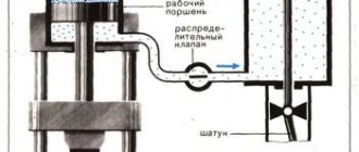
A multimeter is the main measuring tool for any specialist involved in electrical circuits, including an auto electrician. No computer diagnostics can replace this simple device.
Not only every driver, but also any self-respecting man should know how to use a multimeter in a car or at home.
How to use a multimeter in a car: detailed instructions for dummies
Hi all! I think many motorists and just electricians will agree that having a multimeter is very helpful in everyday life. It can be useful in everyday life and when servicing or repairing a vehicle. Therefore, today we’ll talk a little about how to use a multimeter and do it correctly.
You can call the device a tester, a multimeter (MTM) or a tester. Although a tester and an MTM are not exactly the same thing. But I suggest that you don’t get hung up on notations, but simply talk about the current topic.
Using such devices, you can check voltage parameters, the operation of electrical equipment, and measure current and resistance. In general, MTMs are multifunctional devices and should be in every driver’s car.
Why is it needed?
A multimeter is a universal electrical measuring instrument for monitoring voltages, currents and resistances in an electrical circuit. Since a modern car is more likely an electronic device than a means of transportation, the presence of a multimeter in its repair kit is necessary, even if the car owner is not an electrical specialist.
You can learn how to use a multimeter in a few minutes. The cost of such a device is small, it can provide disproportionately great help in the event of a malfunction of the vehicle’s electrical equipment.
Currently, automotive multimeters are produced specifically for use by auto electricians and car enthusiasts. They are adapted to measure electrical and other parameters related to the operation of engine systems, battery charge, and vehicle electrical equipment.
Many multimeters are classified as automotive only as a marketing technique. The parameters they measure do not always meet the needs of auto electricians, especially ordinary car enthusiasts.
Getting to know your device
To begin with, I propose to talk about multimeters themselves as electronic devices. Next, detailed instructions will be presented for beginners or, as they say, for dummies.
Let's look at the front panel of the device for measuring indicators in the car and at home. Typically, several values are indicated on the front. Namely:
As for the 3 connectors. The probes are connected through them. The set with pliers is included with the MTM, so everything should be clear here.
There is one note regarding how and when to connect certain probes to the tester. There is a black wire that invariably always goes into the socket that is marked with the symbols COM.
But with red the situation is more complicated. It all depends on what kind of measurements you are going to take with your digital multimeter. When making measurements of mains voltage, resistance or current up to 200 mA, then you only need the VmA output. If the value exceeds 200 mA, then connect the red probe to 10 ADC.
I think we've sorted this out. If you do the opposite, you will not be able to use the tester for a long time. The reason for this will be a blown fuse. As in the case of the cigarette lighter fuse in a car, fusible elements are also used here.
Analog MTM
Most motorists and electricians prefer digital multimeters. These are modern devices with wide functionality.
But there are also outdated devices on the market. They are called analog or pointer. Whichever is more convenient for you. But their characteristics and efficiency are significantly inferior to digital solutions. Using a pointer tester is not the best option, since the scale has a larger error.
And in general, using such devices is not particularly convenient. It is better to immediately switch to good quality digital devices.
I would include the following models as such:
Instructions for use
Now I’ll tell you in a little more detail about how to use a digital multimeter with your own hands to make different measurements of parameters.
In our material we will consider the measurement:
To make everything more clear, I will tell you about each procedure separately. If you have anything to add to this instruction, be sure to write in the comments.
Voltage
Measuring the voltage yourself is not difficult. But detailed instructions for such a case will definitely not hurt.
The sequence of your actions will be like this:
You can clearly see that there is nothing complicated in this procedure. Therefore, you can easily measure the voltage that is currently observed in the electrical network with your own hands. Both variable and constant.
The main thing here is not to touch the probe with your bare hands, since it will be under the influence of current.
Current strength
To determine the current parameters, the first step is to answer the question of what kind of current flows through the wiring. It can be variable or constant.
Next, you look at the equipment or device to see what the approximate value may be. The indicator is measured in Amperes, that is, denoted by the letter A.
And here, as you can see, you can easily cope on your own. The task of measuring the current strength is completed. Therefore, let's move on to the next point.
Resistance
The simplest and safest measure using MTM is resistance measurements.
Here proceed as follows:
Following these simple rules and consistency in your actions will allow you to quickly and without any problems carry out all the necessary procedures for measuring resistance.
A good multimeter function that often comes in handy when repairing home appliances. For example, I recently fixed my wife’s iron. And the tester turned out to be extremely useful in this work.
Calling
I didn't tell you anything about the back panel of the multimeter. Although there are several more functions there. They are mainly intended for radio technicians who are professional in their work. They will not be needed for tasks at home or when repairing a car.
With the exception of one mode. It is called dialing mode. It is designed to search for breaks in electrical circuits. To do this, the chain needs to be ringed. When it is closed, that is, there is no break, then a sound signal appears. If there is a break, then no sounds will appear. This means that you have found the problem area.
To check, you need to place two probes on both sides of the chain being called. This allows you to find even a minor break in an extended electrical circuit.
I tried to help as best I could. You have comments and questions. Additionally, you can watch a visual video.
I think everyone, if desired, can easily understand the operation of any modern digital multimeter. In addition, the manufacturer always includes detailed instructions for the device. Therefore, you should always start working with the device by studying the instruction manual.
Source
Features of the probe and its operating principle
The continuity probe is structurally a plastic capsule, inside of which a resistor with a high resistance is placed. A metal rod extends from the plastic base, the end of which is used for direct contact with the contacts of electrical equipment. The device shows the presence of voltage; green and red LED lights located on the plastic case act as indicators. The green LED indicates low circuit resistance, the red LED indicates the presence of voltage.
A car test probe, which is essentially a voltmeter, is indispensable when identifying faults in a car's electrical equipment, as well as when installing new electrical equipment on a vehicle.
The diagnostic device makes it possible to determine the integrity of an electrical circuit or a separate section of it, identify locations of broken connections, unreliable contacts, the location of failed parts, as well as identify a number of other damages. To carry out a quick check of current-carrying equipment, the use of a continuity probe is the most rational and expedient solution.
Automotive probe for checking the ignition spark JTC
Automotive probe for checking the ignition spark TEST-M
Automotive probe 6-24V 110mm “needle” brass AVTODELO
Automotive tester 6-48V in a FORSAGE bag
Automotive probe 6-24V 120mm “needle” TECHNICIAN
Car probe for checking the ignition spark 0.5m FORSAGE
Automotive probe 6-24V ROCKFORCE
Automotive probe 6-24V 120mm plastic case SPARTA
Automotive probe for checking the ignition spark FORSAGE
Automotive probe 6-24V FORSAGE
How to find a short circuit in a car wiring
A short circuit is an unacceptable connection of part of a circuit to ground or another part of the circuit. Often the cause of a short circuit is severe oxidation of the contacts in the block, or damage to the insulation of the wires. If, after replacing a faulty fuse, it blows again, there is likely a short circuit in the wiring.
To find a short circuit, disconnect the section of electrical wiring being tested from the rest of the vehicle wiring. Set the multimeter to dialing mode. We connect one probe of the device to a section of the circuit, and the other to the body (“ground”).
- If there is no short circuit in a section of the circuit, the device will not emit sound signals.
- If there is a short circuit, the multimeter will beep (the circuit will be closed).
We inspect the entire section of the chain for damage.
Let us remind you that it is more convenient to carry out wiring diagnostics when you have the car’s electrical circuit diagrams at hand (for Lada XRAY, Vesta, Largus, Granta, Kalina, Priora, Niva 4×4).
Key words: universal article
An automobile continuity probe (also known as a probe) is a diagnostic device that is widely used in servicing electrical equipment of cars. The main area of application of a continuity probe is as a probe for electrical circuits of a car with high input resistance.
The use of a continuity probe for testing various types of electrical equipment
Battery check
Using a probe, you can check the presence of voltage at the battery terminals. To do this, using an alligator clip, you need to connect to the battery terminal with the “-” sign, and attach the end of the probe to the terminal with the “+” sign.
Checking the fuse
To check the fuse, touch one end of its terminal to the positive terminal of the battery, and the end of the probe to its second terminal.
Checking the incandescent lamp
To check an incandescent lamp with a continuity probe, place one terminal of its base to the positive terminal of the battery, and attach the end of the probe to the second. When testing a light bulb with two filaments (such as a car headlight bulb), test them one at a time.
Useful do-it-yourself autotester for lamps
To check the functionality of a fuse or lamp, the car enthusiast has to remove them from their sockets. All this takes up quite a lot of precious time. To greatly simplify this task, experienced craftsmen have developed a special tester. It allows you to check lamps without removing them from their sockets. In addition, such a device also has a number of additional, very useful features.
To make a homemade electronic tester you will need two red and green LEDs, a pair of resistors, a round coin cell battery, some stranded wire, an alligator clip and a small plastic box.
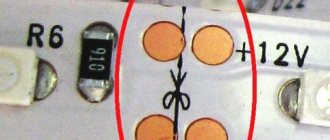
The operating principle of the device is very simple. If the lamp or fuse being tested is working, they close the contacts. Current from the battery passes through them and lights up the green LED. If the contact is broken, there will be no green signal. The red LED indicates the presence of external power at the tested object. A detailed diagram of the product can be found on the Internet, on any site dedicated to this topic.
Assembly begins by connecting the parts. For a round battery, it is better to find a special block. Such devices can be found on the remote control of Chinese-made car radios. Two wires are connected to the power source. Then two small holes are drilled in the body of the future tester and LEDs are glued into them. Their legs are connected to resistors.
The tester probe is made from a thick needle from a medical syringe. It is shortened a little and the contact of the resistor from the red LED is inserted into the hole so that it protrudes slightly outward. After this, the base of the needle is glued to the body with a heat gun. All remaining wires are connected according to the diagram. To secure the parts, the internal space in the tester body is filled with hot glue. At the end of the work, close the housing cover.
The tester does not have a switch and is always ready for use. To use it, apply the alligator clip to one fuse contact, and the probe to the other. If the green LED lights up, the part is operational. Lamps in sockets are checked in the same way.
You can check the presence of voltage and its polarity on the wires. To do this, the tester clamp is connected to one contact, and the probe to the other. The red LED that lights up indicates the positive wire on the probe. Indication by a green LED means there is a negative contact on the probe.
Checking a car relay
In addition to the electromagnet winding, an automobile relay also has contacts that, over a long period of operation, can burn out and, as a result, stop switching electrical circuits. Using a continuity probe, you can check both the integrity of the electromagnetic winding and the serviceability of the contacts.
To check the relay winding, you need to attach one of its terminals 85 or 86 to the battery terminal with the “+” sign, and attach the end of the probe to the second terminal. The serviceability of the contacts is determined by touching the terminal of the moving contact 30 to the terminal, and by touching the terminal 87a with a continuity probe.
In the same way, any microswitches and switches are checked.
Advantages of using a test probe
Diagnostic equipment of this type is distinguished by its functionality and ease of use. Due to a malfunction of electrical equipment, all components of the vehicle may fail. The probe allows you to quickly identify the cause of the malfunction, determine the circuit elements that need to be repaired or replaced, and also make repairs or replacements with the creation of the correct electrical circuit.
A car test rod is an inexpensive device that should be in the toolkit of any car owner.
Driving for a long time leads to fatigue of the neck muscles and harms the health of the spine. Headrest pillows help solve these problems. Find out about what headrest pillows are and why they are needed, as well as about the range, selection and use of these accessories - from the article.
To cut external threads using round and rectangular dies, you must use a special device - a die holder or a die driver. Read all about the knobs, their existing types, design and characteristics, as well as the selection and use of these devices in the article.
Threaded fasteners are simple and reliable, but damage to the bolt or stud may make it impossible to remove and replace. This problem can be solved using a special tool - a set of extractors. Read about these devices, their types, design, selection and application in this article.
Feeling the breath of winter, all motorists are thinking about replacing seasonal tires. And many of us, when buying winter tires, are faced with a difficult choice - “studded” or “Velcro”? Each type of tire has its own advantages and disadvantages, and choosing one over the other can be very difficult. In this article we will try to make this difficult choice.
Filling the tank with low-quality diesel fuel can damage the engine until it completely fails. Special auto chemicals—diesel fuel additives, which are described in detail in this article—help to minimize or eliminate the negative consequences of refueling with low-quality diesel.
Using the right type of tires ensures your car has stability and controllability in any driving situation. Only seasonally used tires guarantee optimal grip on the road surface and minimal braking distance.
In addition to the main direction indicators, all motor vehicles must have auxiliary lights - side turn signal indicators. Read all about repeaters, their classification, design, characteristics and operation, as well as about the selection and replacement of this type of device.
Source
Review of popular models
Let's look at some models of automotive multimeters.
F716
Manufacturer: Caltek Industrial. Designed to perform the following measurements:
- current, voltage and resistance in the mode of a conventional multimeter;
- checking the presence and parameters of fuel injection pulses (nozzles, injectors);
- checking lambda probes;
- control of the battery charging system;
- measurement of battery leakage current;
- grounding quality control;
- availability of an RS-232 bus for connecting to a laptop.
In principle, these functions, with the exception of measuring injection parameters and connecting to a computer, can be implemented on a regular multimeter.
Mastech MS6231
Purpose:
- measuring parameters in the mode of a conventional multimeter;
- temperature measurement ranging from minus 20 to plus 1000 degrees Celsius;
- crankshaft speed measurement;
- measuring the crankshaft advance angle (contact ignition);
- auto power off;
- retention of measurement results, maximum value.
The most useful function is auto power off; it will prevent the battery from discharging when work is completed. The engine speed is shown on the car's tachometer; contact ignition systems are used only on Zhiguli cars.
MS8211
It features an original shape. Among the very useful functions of this multimeter, in addition to a powerful flashlight (which is sometimes very useful), is the ability to non-contactly monitor the voltage (current) in a conductor without damaging the insulation. Experienced auto electricians know how often it is necessary to pierce a needle or make a micro-cut to check the voltage in a particular conductor.
Using the special probe of this multimeter, you can check the circuit without damaging the insulation. Non-contact voltage monitoring can also be done for a household AC 380 Volt network (with the appropriate position of the mode switch). The automultimeter also has a “control” (a light for dialing).
Video - review of such a multimeter:
The following are offered as special automotive measurements:
- checking for short circuits and open circuits;
- ignition system test;
- generator control;
- control of injector pulse parameters.
A very original and useful device.
UNI-T UT105
In addition to the usual functions of a multimeter, it measures engine speed. For “dummies”, the display shows which connectors to connect the probes to in a given measurement mode. Very original, but nothing more.
Video - UT105 car multimeter in operation (function overview)
Fluke 88V
The American manufacturer equips the multimeter with additional probes, alligator clips, a tip for high-voltage wires, and a temperature sensor. In general, the measuring instrument can be classified as professional.
In addition to the usual ones, the multimeter measures the parameters of injector pulses, including duty cycle, crankshaft rotation speed. There is a megohmmeter up to 40 MOhm, very useful for monitoring high-voltage wires and spark plugs. The bells and whistles include a quasi-analog scale on a digital display and automatic setting of the measurement limit. Not a bad device.
Trisco DA-400
Almost an ordinary multimeter with additional functions of “continuity”, temperature measurement, a non-contact probe for high-voltage wires, measuring the ignition angle (this is a big plus), measuring direct current up to 15 Amps (not 10, as in most - and this is a plus).
The manufacturer claims shock resistance when dropped from a height of 1.5 meters (this is a double plus). At a low cost, such a device is almost ideal, both in the practice of an auto electrician and for a car enthusiast. One problem is that it is quite difficult to find it on the radio and car markets.
Tags: multimeter, probe.
Comments 70
In general, I don’t trust purchased probes made from the body of a cigarette lighter plug... I have my own “eternal” probe scheme, which has never failed. two diodes, two LEDs, two resistors, and a 4-6 volt battery from an autonomous siren
About the oxidized and destroyed wire inside the insulation:
The question is how to find out the reference resistance of the wire, given that the terminal contacts are 1 ohm each (=2 ohms)? ... I’m sitting here scratching my head. I’ll be very glad to help. In a jeep, on the floor, wires go in a bunch, from the hood, under the car, to the gas tank and level sensor. The total length is about 5 meters (maybe more) How to ring them, assembled? To understand where the sausage is, in the terminal blocks, or the wires themselves? And if you pierce sections of wires, what is the best way to seal them so that they do not collapse? … Thanks in advance.
Only with light bulbs can the field assembly in the module be burned. You have to be careful with them.
Not everyone in the comments admired it, I immediately said that he was bullshit and gave an example that because of the fuse block only 10V was coming to the pump, and this crap would show that there is voltage.
I meant the overwhelming majority, those who are not in the subject.
I completely agree with every word you wrote.
One old auto electrician showed the starter of a ZIL. I took a light bulb with one cut wire and actually connected it in series with ground and the stator windings, smoke appeared in the place of weak insulation, insulated the winding, checked it again - the norm. Then, in series with the ground and the brush assembly, a microcrack filled with coal dust was discovered in one of the insulators, also sparking and smoke, replace the insulator, control check - the norm. Of course it’s a violation of TB, but you can foolishly tighten a nail with a screwdriver. I used it myself and it helps.
Among the instruments, the auto electrician did not see a 220 V 80-100 W light bulb with a break in one wire for diagnosing starters to determine the point of short circuit (brush assembly, etc.) to ground. Is this option available?
There were no problems with the starters, or with their diagnostics. And I didn’t know this method, can you tell me more?
An excellent sample, I’ve already erased about thirty of them)) I use them as a consumable. One minus: 24V batteries explode, they don’t last long. You just need to approach any testing by a tester headlong.
Each tool has its place in the work. You need a multimeter, a tester, an LED, and a postulograph.
Source
Auto electrician tester for ATmega
Probe specifications:
- Supply voltage 6-12V.
- DC voltage measurement range 10-32V.
- Sound verification.
- Determination of voltage polarity.
- Illuminated probe needle.
- Operating temperature 0 - +60 °C.
- Board dimensions 100x25 mm.
Description of probe operating modes
I made two modes of operation, this is a voltmeter mode and the continuities are switched by a switch on the board, for convenience it can be output to the case.
In the dialing mode, the needle has a constant voltage of no more than 5V. In voltmeter mode there is no voltage on the needle, and the resistance between the minus and the needle is 14 kOhm. Therefore, you cannot use this probe to look at signals on injectors, sensors and other circuit elements! It is designed to test power circuits, charging, and search for broken wires (in other words, it is still a multifunctional light bulb)!
To test electronic signals from sensors, CAN buses, loads, I am developing version ver2.0 of this probe!
Voltmeter mode: LED indication, consists of 7 LEDs divided into measurement ranges—->
- 10V-12V
- 12V-13V
- 13V-24V
- 24V-27V
- 27V-30V
- 30V-32V
- 32V
Dial mode: In this mode, the polarity is determined, if there is a minus on the needle, then the sound signal beeps, if it is positive, then the HL8 LED lights up. In this mode, you shouldn’t hold the plus on the needle for more than 10 seconds (I think this time is enough), since the load resistor R13 heats up (it simulates a light bulb load, the incoming load on the needle depends on its power in this mode) in the stabilizer, so as not to lead to building a microcontroller. Also, by connecting the needle and the crocodile, a signal sounds to check the wires for a break.
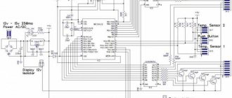
Circuit and assembly: The probe circuit consists of available parts, resistors R1-R7, R12 are selected based on the current consumption of your LEDs, mine are 300 Ohms, resistor R13 with a power of at least 1 Watt. Transistor VT1 Kt3102 or analogues, emitter BA1 with a built-in sound generator, and not just a speaker, zener diodes VD1, VD2 at the probe input are for protection (it is not recommended to supply more than 32V, otherwise you can burn the probe ). Resistors R8.R9 should be chosen with a smaller tolerance spread % and a power of at least 0.25 Watt, for measurement accuracy! A few words about the firmware, just upload the HEX file and that’s it, you don’t need to flash the fuses, we leave the factory ones (works at a frequency of 1 MHz from the internal oscillator), I made it easier, the speed of the probe is of course a little lower, but it will be much easier, especially for beginners, when programming a microcontroller .
Assembly drawing of the board
View from above:
Side of tracks:
Initially I wanted to make an SMD version, but I ran out of photoresist and so I decided to do it the old fashioned way using an iron and printer, which is why the tracks are so thick). I didn’t take a photo of the board, it became too ugly while it was being tested!
Well, as for assembly, everything is extremely simple, the only thing I can advise during installation is to solder jumpers (6 pieces) first into the board, highlight them in red, mark the positive leg of the BA1 emitter with a + on the board, board size 100x25mm. The HL8 LED can be placed in a convenient place on the case to see the positive indication in the wiring. The archive contains a printed circuit board in TIFF format (the print can be opened with any PDF viewer, DjVu, for example, the free STDU Viewer) and firmware in HEX format!
Happy building, my friends!
List of radioelements
| Designation | Type | Denomination | Quantity | Note | Shop | My notepad |
| IC1 | MK AVR 8-bit | ATmega8 | 1 | Search in the Otron store | To notepad | |
| DA1 | Linear regulator | LM78L05 | 1 | Search in the Otron store | To notepad | |
| VT1 | Bipolar transistor | KT3102 | 1 | Or analogues | Search in the Otron store | To notepad |
| VD1, VD2 | Zener diode | 5v1 | 2 | Search in the Otron store | To notepad | |
| R1-R7, R12 | Resistor | 300 Ohm | 8 | Search in the Otron store | To notepad | |
| R8, R10, R13 | Resistor | 2 kOhm | 3 | Search in the Otron store | To notepad | |
| R9 | Resistor | 12 kOhm | 1 | Search in the Otron store | To notepad | |
| R11 | Resistor | 1 kOhm | 1 | Search in the Otron store | To notepad | |
| C1, C2 | Capacitor | 100 nF | 2 | Search in the Otron store | To notepad | |
| C3 | Capacitor | 10uF*10V | 1 | Search in the Otron store | To notepad | |
| HL1-HL8 | Light-emitting diode | 8 | Any select by current | Search in the Otron store | To notepad | |
| HL9 | Light-emitting diode | 1 | Used from a lighter with a flashlight | Search in the Otron store | To notepad | |
| BA1 | Squeaker | TMB12A05 | 1 | Search in the Otron store | To notepad | |
| Add all | ||||||
Attached files:
- avto.rar (4 Kb)
How to test the wiring in a car yourself with a multimeter
People have long lived surrounded by electrical appliances, which have quietly entered the life of every person since childhood. Electronic watches, electric kettles, telephones, computers, cars are indispensable human assistants in everyday life and at work. But sometimes devices break down and you have to check and repair them. There is nothing difficult about this if you know how to use measuring instruments and know, for example, how to test the wiring in a car with a multimeter or how to check the integrity of an electrical circuit.
General information
If a connection is found, then if there is a built-in speaker, the device emits a sound signal. This is where the term “call” comes from. The device rings if there is a connection. A multimeter can also indicate that there is no connection between elements and helps determine a short circuit. Using the tester, all kinds of radio components are checked: resistors, transistors, diodes, relays, capacitors, and so on.
Conductor continuity is based on Ohm's law for a section of an electrical circuit. Ohm's law states that the resistance of an element is equal to the ratio of the applied voltage to the magnitude of the current in a section of the electrical network. Resistance is measured in Ohms. A resistance of one Ohm indicates that a current equal to one Ampere flows through the conductor at a given voltage of one Volt. Based on the calculated data on resistance, conclusions are drawn about the results of the call.
That is, a certain voltage is set on the multimeter, and the current value is determined using the instrument scale and the resistance is calculated. In other words, the multimeter is a voltage source and an ammeter to measure the resulting current.
Device structure
Devices may differ in appearance, but multimeters are fundamentally divided into analog devices and digital devices.
Analogue devices are already gradually being replaced from the market by digital ones, but in the homes of many home craftsmen you can still find analog devices.
Such devices are equipped with an indicator screen with a scale and arrow. The advantage of these models is the clarity of display of measurements. The deflection of the needle is visually easier to assess than the flashing of numbers on the electronic display of digital instruments. Often, when making a call, it is necessary to evaluate approximate resistance indicators or, in general, its presence or presence, so analog devices are suitable for most practical work.
Digital multimeters have more complex electronics and a digital display. This type of device is used mainly in production and industry.
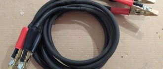
The housings of all multimeters have outputs for two probes. These are two insulated wires ending in needle-like metal tips. In some cases, special clips, so-called “crocodiles,” are put on the nozzles. When choosing a device, you need to pay special attention to the quality of the probes. The correctness of measurements depends on them.
The wires must be flexible with strong soldering and fit well into the device sockets. It often happens that outwardly spectacular probes are of unsatisfactory quality and have poor technical characteristics.
Operating principle
The analog type of the device does not require its own power supply .
Its operating principle is the same as that of an ammeter, and an analog device works best in the range of radio waves and electromagnetic fields. There are induction coils inside the device body, and when the probes touch the conductor, a current begins to form in the coils. The created magnetic field deflects the indicator needle to a certain angle. The magnitude of this angle depends on the strength of the current generated, and the arrow on the drawn scale indicates the measurement value. Digital devices contain a textolite printed circuit board on which a digital chip , which is responsible for processing the received data. To operate the electrical circuit and screen, digital devices are powered by batteries or an external power source.
Digital multimeters have lower measurement uncertainty and are more accurate than their analog counterparts.
There is a switch on the front panel of the multimeter that selects the measurement mode. The switch sets the scale factor that determines the value on the device scale.
Analog instruments have two types of scale:
The uniform scale is very sensitive to overloads, so the switch is first set to a large scale factor value, which is gradually reduced. The logarithmic scale does not have this drawback and has a range of values from zero to infinity.
Thus, the main components of multimeters are:
Continuity of wires
Before starting any measuring work, it is imperative to check the serviceability of the tester itself.
It happens that the measuring system itself is faulty. To check, the ends of the probes of the measuring device are in contact. If the device is operational, the indicator will display zero or deviate slightly. A slight deviation indicates that the probes and terminals have their own small resistance.
If the multimeter has a sound signal, then the device is set to buzzer mode. This is done by placing the switch on the corresponding icon on the tester body.
The probes are brought to the ends of the part being tested.
Possible tester behavior options:
When taking measurements with a multimeter, do not allow the human body to come into contact with probes and wires where there is no insulation.
How to find a broken wiring in a car
If there is a break, the electrical circuit opens. Often the cause of lack of voltage is poor contact in the circuit connector. The block body hides oxidized contacts, so troubleshooting can take a long time. A break may be detected when the pads or wires are swayed.
To find a break in the test, you need to set the multimeter in ohmmeter or continuity mode. The terminals of the device are connected to the ends of the circuit being tested:
- If there is no break, the multimeter will beep (in dial mode) or the resistance will be minimal (in ohmmeter mode).
- If there is a break in the wiring, there will be no sound signal (in dial-up mode), but the resistance will be very high (in ohmmeter mode).
Troubleshooting in a car's electrical circuit
If some component in the car does not work, then first of all you need to check the electrical circuit. There are no particular differences between how to test different wires in different cars with a multimeter, except for the high-voltage cable.
First, make sure that there is voltage in the circuit of the non-working unit:
If the tester indicator shows the presence of voltage, it means the wire is intact. By analogy, all wires of the node are called. If the wire is damaged, the multimeter scale shows zero.
It must be taken into account that in some areas of the car voltage is supplied only when the ignition key is turned on.
When the voltage check is completed, the current value is checked. The device is switched to ammeter mode, the switch selects a measurement range of up to ten amperes. All vehicle devices must be turned off and the tester must be properly connected to the vehicle's electrical network. To do this, a multimeter is connected between the positive terminal of the battery and the unit being tested. The device screen should display the found current value; it should correspond to the consumption of constantly switched on devices of the machine. If the current value exceeds the norm, a conclusion is drawn about its leakage.
In this case, they begin checking devices that are not included in the standard equipment of the car, and places where wiring is part of moving mechanical components.
Experienced craftsmen identify areas with a drop in current, focusing on the readings of a multimeter with the fuses removed one by one. Then check for sparking at the contacts.
If a misbehaving wire is detected, it is ringed to check its integrity, and then its resistance is measured.
One of the answers to the question of how to test wires with a multimeter is to measure the resistance of each of the wires of the node. The rating is applied to the braid, and a tester is connected to the wire in ohmmeter mode. Typically, the range of resistance values for automotive wiring ranges from 3.5 to 9.9 kOhm. The difference between the measured element and the norm should not be more than four kiloohms.
Which multimeter is better for an ordinary car enthusiast to choose for a car?
In principle, when choosing a multimeter for automotive use, it does not matter whether the car or a regular model of the device will be located in the trunk. If a multimeter is purchased for garage storage and use, then you can choose a car model.
The main thing is that you should always have a multimeter in your car!
It doesn't matter which one. In emergency situations of electrical equipment failure on the road or in a parking lot, it is usually necessary and sufficient for the multimeter to produce:
- measuring the voltage of the on-board network and battery;
- monitoring the battery charge from the generator;
- made a “test” of fuses, light bulbs and electrical wiring;
- leakage current measurement;
- monitoring sensor parameters, primarily resistance and voltage on the sensors.
The following additional consumer characteristics are desirable: backlighting of the digital indicator, shock-resistant housing. A simple multimeter costing up to 1000 rubles, for example MAS830L, can satisfy these parameters.
The designations of modes on most devices are standardized, therefore, having learned to work on one multimeter, you can confidently switch to using another. The “lifetime” of a multimeter in the practice of an auto electrician is a maximum of six months, in a car enthusiast – a couple of years.
The first thing to fail is the probes. This usually happens in winter: poor-quality insulation cracks in cold weather, wires break, and probes have to be replaced. Then, usually due to inattention, the 10 Ampere current measurement mode fails. After this, the dialing mode, resistance measurements and ... then it’s better to buy a new one. Therefore, it makes no sense to buy an expensive multimeter.