From faulty devices you can extract a large number of different spare parts, which can be used not only to repair other devices, but also to independently manufacture original products. One of these useful homemade crafts is spot welding, which is quite easy to make from unwanted microwave ovens.
Don't throw away your old microwave
How to make a spotter yourself from an old microwave will be discussed in detail in this article.
How it works: nuances
First of all, let's look at the spotter function.
It is needed for only one operation: repairing a crumpled body surface without a general disassembly of the entire body. It is most valuable when repairing hard-to-reach parts that need to be straightened during the repair. The spotter can be made from an inverter, or from a battery or transformer - there are several possible electrical circuits. The principle of operation of the device is a reverse action hammer, working in a point manner.
Most often, the spotter has the following operating modes:
- Short-term mode, in which the guide is attached to the required local location using special rings.
- Welding mode is the main one, which is carried out at minimum power and using carbon electrodes.
Application
During the straightening process, the electrode is welded pointwise to the dent and, with the help of an inoppuller used as a return striker, is pulled out. In this case, the tack breaks, the electrode is displaced and the straightening process is repeated again. Gradually, point by point, the dent is leveled out.
The spotter is used for straightening metal bodies . The dent should be cleaned from paint to bare metal. The clamp of the second pole is attached to the area of the body being leveled next to the area being treated. The main condition is the occurrence of a short arc between the part and the electrode.
Making a pistol
Without a pistol, the spotter will not perform its functions. This component is also known as studder. The choice of operating mechanism depends on the intended purposes. Spotter pistols are divided into two categories:
- factory;
- homemade.
To work with a high frequency of spotter use, factory models are purchased. Such devices are capable of providing sufficient performance for the assigned tasks for a professional welder.
A homemade spotter gun is recommended for use in household work where a heavy load on the equipment is not required. The following are used as homemade working mechanisms:
- glue gun;
- semi-automatic welding machine.
To make a handle for a studder, getinax or textolite is used. The thickness of the material ranges from 12 to 14 millimeters. Two rectangles of the same size are cut out of it.
A niche is created in one of the segments to accommodate the fastening element. This part of the workpiece is intended for fastening:
- electrode - a copper rod with a diameter of 8 to 10 millimeters;
- light bulbs;
- buttons that turn on the backlight;
- switch that supplies the pulse.
The button must be placed strictly in the created recess. A homemade bracket is used as a fastening element. A pipe made of copper is used for its production. It is necessary to obtain a square or rectangular cross-section.
The gun is connected to the spotter using a five-core welding or control cable. The cores are connected to:
- switch;
- backlight bulb;
- switch light.
The end of the cable is placed in the hole in the bracket and secured with a soldering iron. Before this, it must be cleaned.
Diagram of a spotter based on a welding machine
For a craftsman who has minimal skills in electrical engineering and uses a self-assembled device to repair his own vehicles and the cars of friends, a device based on an old medium-power welding transformer with a simple control unit is quite sufficient.
In this case, the best option is a spotter control system made from simple and accessible parts, the diagram of which was published in the “Modeler-Constructor” magazine (see below).
Spotter circuit
The author uses a serial welding transformer with a power of 1 kW with a primary winding of 200 turns (any other one with similar characteristics can be used). He replaced the secondary with two parallel windings of 3 turns with a total cross-section of 100 mm².
The calculated open circuit voltage according to this circuit is approximately 6.5 V. S1 is the input circuit breaker of the device. S2 is a shutdown button, when closed, voltage is supplied to contactor K1 and its contacts K1.1 and K1.2 open. Control over the duration of the welding process is visual.
In principle, it is easy to supplement this scheme for controlling a spotter from a welding machine with a time relay (including electronic) and a current control system.
In the video (see below), the author of the homemade device used exactly this circuit, only instead of a contactor he uses a low-voltage relay powered from a rectifier. For a spotter, this is the only correct solution, because in this case, a safe voltage is supplied to the button located on the working gun.
Design Features
A spotter is a device for one-sided spot welding used in body repair. The design of the device is quite simple, so it is not necessary to buy it for a lot of money.
The spotter is used to straighten dents in metal
To make a spotter, you can take both an electrical transformer and a metal case from an old microwave oven. But it is necessary to take into account some features of a homemade design:
- A do-it-yourself spotter will be inferior in power to the factory unit. It can be used in a home garage, but if we are talking about professional repairs, it is better to purchase the tool for money.
- A homemade spotter made from a microwave oven requires greater effort when straightening the body and does not allow work to be carried out at high speed. True, for beginners this becomes more of a plus; with careful and leisurely alignment of the dent, there is less risk of making a mistake.
How to make an electrode for a spotter
Spotter electrodes and adapters are small cylindrical attachments made of brass, each of which is used to work with certain types of welding fasteners: washers, nails, studs, crimped wire rivets. In stores, each of these elements can cost from 500 to 1000 rubles or more, and for ordinary body work you need at least five or six types of electrodes:
- for rings;
- for spot welding;
- for corrugated wire;
- for welding with carbon electrode;
- for triangular washers;
- for pins and nails.
Making them yourself is not so difficult, but it requires certain skills and the availability of appropriate equipment. Alternatively, you can make only the simplest attachments with your own hands, and order more complex ones in a workshop with turning and drilling equipment.
In battery spotters, batteries with a capacity of 40÷60 Ah are usually used as a power source. If anyone has had to work with such devices, please write in the comments: how quickly the battery discharges and how the quality of welding changes as it discharges.
From faulty devices you can extract a large number of different spare parts, which can be used not only to repair other devices, but also to independently manufacture original products. One of these useful homemade crafts is spot welding, which is quite easy to make from unwanted microwave ovens.
Don't throw away your old microwave
How to make a spotter yourself from an old microwave will be discussed in detail in this article.
Recommendations
When assembling a spotter with your own hands, you need to take into account several important nuances:
- The new secondary winding for converters must be covered with a layer of reliable insulation.
- The control unit for a homemade spotter based on a microwave oven can be made independently using the appropriate diagrams or purchased ready-made. In the latter case, the process of creating a welding unit will be reduced to searching for current converters and installing the device elements into the housing.
- When working with a spotter, do not press the pulse button for long. The welding effect should be short but powerful. It is to ensure the latter condition that the unit is made using two or three electrical transformers simultaneously.
Features of a homemade device
A homemade device is less productive than professional equipment from car dealerships. For repairing your car, it has the following advantages:
- cheapness;
- DIY repair ability;
- small size.
In terms of power - welding force, a homemade spotter is inferior to a ready-made spotter from a store . This is a plus of the equipment. Body straightening requires skill. Low effort allows you to gradually, little by little, level out the dent, without fear of making a mistake.
Anyone who knows how to do mechanics and understands electrical circuits can make a spotter with their own hands. The equipment is necessary in every garage, although it is not constantly used.
Main components for assembly
To assemble and test a homemade spotter, you need the following components and consumables:
- Frame. Sheet metal box structure with front and back panels. Ventilation holes and a ground terminal are required.
- Power supply. In its simplest form, it is a do-it-yourself transformer with a circuit breaker in the primary circuit.
- Power cables. The welding cable must have a terminal for connection to power and a threaded contact for connection to the gun, and the ground cable must have a terminal and contact pad for welding connection to the body part.
- Control circuit. The minimum version includes a switch button on the gun, an input voltage cut-off relay, control wires and a control circuit power supply.
- Welding gun. At one end there is a contact threaded connection for connecting electrodes and adapters, and at the other there is a socket for connecting a welding cable.
- Equipment. The basic version includes electrodes for washers and pins, a return hammer and an adapter for connecting a carbon electrode.
Assembling a reverse hammer (inopuller) with your own hands
In order to assemble a reverse hammer with your own hands, you need the following parts:
- steel rod 60 cm long, 17 mm in diameter, with threads on both ends;
- steel bushing with a through hole with a diameter of 15 mm, a length of 15 cm and a diameter of 40 mm;
- return spring;
- travel stop nuts and washers;
- adapters for attaching electrodes.
First, a washer is put on the end of the rod intended for fastening into the gun and the nut is tightened tightly. The rod is then passed through the bushing and return spring. The final step is to attach a washer and nut to the bottom threads, and then screw on the electrode adapter. During operation, the massive bushing will be repelled by the spring and perform reciprocating movements between the two washers.
Making a working pistol
Branded spotter pistols are usually produced in the form of devices with a pistol grip. Much of what folk craftsmen make with their own hands can only conditionally be called a “pistol.” Often it is just a cylinder with a button and a terminal for connecting a cable at the end. This is because the spotter gun consists of only three parts: the body, the contact rod and the switch. The contact rod is usually made of brass. At one end there is a thread for attaching a reverse hammer, and at the other there is a clamp for connecting power. For those who make such devices with their own hands, whether to place it in a pistol case or use it as is is a matter of personal preference. At the same time, despite the low welding voltage, it must be insulated: these are the requirements of safety regulations.
Transformer for spotter
Any transformer is suitable for making a power source for a spotter. Videos of the manufacture of spot welding machines based on transformers of microwave ovens and other household appliances are distributed on the Internet.
At the same time, the authors of these crafts do not inform what current their devices are designed for, and this is very important, because
The penetration of the metal surface during operation of the spotter should occur in a fraction of seconds, without appearing in any way on the back side of the part. Factory devices have a power of 3÷5 kW with an open circuit voltage of 7÷8 V (welding voltage - 1.5÷2 V).
For a spotter assembled by yourself and intended only for body repairs, a power of 1.5÷2 kW is sufficient. It is not difficult to calculate how many turns there should be in the secondary winding of a transformer. To do this, the number of turns of the primary winding (new) must be divided by the quotient of 220 divided by 7 ÷ 8. Usually it turns out just a few turns.
Control unit diagram
There are quite a lot of electronic circuits on the Internet that are labeled as spotter control units. Some of them refer to industrial designs of spot welding installations (including old ones), others are replete with electronic components and have redundant parameters, and a number of circuits are not at all related to our topic. Many of the proposed devices implement adjustments to the open circuit current and voltage, as well as control of the duration of the welding pulse. Their manufacture requires a certain skill, and the parts used are not that cheap. Choosing one of these schemes is advisable if you plan to make a spotter for commercial use in a small auto repair shop. And for devices that are made by hand and used at home, there are simpler solutions.
Manufacturing of controls
In order for spot welding to be simple and convenient to operate, it is necessary to manufacture a device body with which it will be possible to easily weld metals.
The first thing you need to do is fix the transformer. For this purpose, you can use a thick plywood sheet, in which holes are made with a drill to mount the transformer. The spot welding process can be controlled as on a remote machine, when the transformer is located separately from the body and from it voltage is supplied through wires to the pincer contacts. Such a device will allow you to perform welding work in hard-to-reach places and on large objects.
A significant disadvantage of the remote apparatus is the need to use a sufficiently long cable, when passing through which the electric current will be significantly reduced due to heating of the conductor at the time of welding the metal. Also, the disadvantages of the remote device include the inability to use pliers with a long lever, so the contact force will be insignificant, which cannot but affect the quality of welding.
You can make pliers yourself if you have an inverter welding machine. To make pliers, you will need to find 2 large spacer washers with a thickness of at least 8 mm and a diameter of 50 mm. If suitable parts are not available, you can make them yourself on a lathe. If you make the washers yourself, then in the middle of each of them you will need to make a hole with a diameter of 20 mm.
The next step in making pliers yourself is cutting out insulation from a thick ebonite rod.
It is advisable to select the rod in such a way that its diameter coincides with the outer diameter of the metal washers. The middle insulation is made as follows.
- A piece 30 mm long is cut from the ebonite rod.
- The ebonite washer is securely fixed in the drilling machine and a through hole with a diameter of 8 mm is made exactly in the middle.
- On a lathe, material up to a diameter of 20 mm is removed from both sides of the ebonite washer. Removal of material should be carried out at a distance equal to the thickness of the metal washer.
This will create a reliable insulator that will prevent a short circuit between the arms of the pliers.
At the next stage of making homemade pliers, handles about 40 cm long are welded to metal washers on one side, and the contact part of the device on the other, to which the power cable and clamp for electrodes will be attached. The handles and contact part of the device can be made of a metal rod, which should be straight on the operator’s side and L-shaped on the contact part. The bending of the pliers on the side of the working part is necessary so that the contacts make contact only at the place where the parts are welded. After completing the welding work, the metal washers to which the handles and contact parts were welded are cleaned with a file or emery so that after assembling the pliers, the parts slide freely over the ebonite insulation.
Assembly of homemade pliers is carried out as follows:
- A metal washer is put on a bolt 50 mm long and 8 mm in diameter, then a washer made of any insulating material with an outer diameter of at least 30 mm.
- One half of the pliers is installed.
- A separating ebonite insulator is installed.
- The second half of the pliers is installed.
- An insulating washer is placed, then a metal one, after which the M8 nut is screwed on.
In addition to a significant loss of power on the conductor, when using pliers it is not always possible to make contacts with the required force. This drawback is especially noticeable when resistance welding of metal parts with a thickness of 0.5 mm and above. To ensure sufficient force, do-it-yourself contact welding from an old microwave is made in the form of a stationary machine.
Stationary welding machine
Spring for lever
All the main parts of this type of resistance welding are manufactured according to the principle described above, but with the only difference that the movement of the working part is carried out only in the vertical plane, and the contacts, due to the presence of a longer lever, are closed under a significantly greater force.
In a stationary device, only the upper lever is movable, which, as in the manufacture of pliers, must be reliably isolated from the main body using an ebonite insert.
The use of one lever greatly simplifies the control of the welding machine, and also makes it possible to produce a mechanism that automatically turns on the device when the lever is moved down.
You will also need to equip the lever with a spring, which will return the upper contact immediately after the pressure is released.
There is no need to equip a stationary structure with scissor-type levers, so it is enough to make one movable upper lever on which a clamp for connecting the wire from the transformer and a mechanism for fixing the electrode will be installed.
The lower part is made in the form of a fixed platform with an element protruding upward, on which the power cable and the lower working electrode are also fixed.
Spot welding with a homemade device
The advantage of a stationary device is that this device easily welds metal up to 1 mm thick. Higher power is achieved due to the fact that the transformer is installed
on the same platform as the working part. This arrangement minimizes electrical current losses by using a shorter cable between the secondary winding and the electrodes.
Welding pliers
We recommend reading our other articles
- Simplicity and convenience of purchasing cable products from a reliable supplier
- Drill storage
- Features of drilling water wells
- Impregnation for wood for outdoor use
The pliers for my microwave spot welding were made from a 15 mm profile pipe; a support from a piece of profile was installed at the bottom of the lower part so that the device would not tip over when pressed hard.
The handle is a piece of a 12 mm hexagon and a file handle. Fastening the pliers - 2 corners purchased at a hardware store.
By the way, the electrodes are specially attached to the pliers at the corners so that their angle of inclination can be changed.
Homemade spotter controls
Making a homemade spotter from microwave parts is absolutely easy. Any master can handle this. But in order for the spotter to be comfortable to use, you should take care of convenient and reliable controls. First of all, this concerns the power supply system.
Microwave spotter - connection diagram
It is not enough to remove the power cord from the housing. It is irrational to constantly plug and unplug an extension cord into an outlet. The device can be constantly connected to the electrical network.
But to turn on the device, you need to provide a switch and a power-on indicator on the case. You can use a lever or push-button switch with two positions and a power indicator light. This will save the technician from constantly plugging in and unplugging the power cord into the outlet, and will reliably indicate the status of the device.
To supply an impulse to the electrode of a homemade spotter, the power cable is connected through the power button, which does not have a locking mechanism. The button can be borrowed from any old hand drill, grinder or similar tool. All live parts and connections must be reliably insulated.
Accessories for straightening
In addition to a properly manufactured spotter, you need to select consumables for it in advance and make the optimal configuration for the spot welding machine. Their independent production is not recommended - poor quality will affect the straightening and appearance of the body.
Consumables and components:
- Reverse hammer. Combines the functions of an electrode holder and a mechanical leveler. Cost – from 5800 rubles.
- Washers of various shapes. Necessary for fixing the straightening tool.
- Electrodes. With their help, the active part of the reverse hammer and washers are welded.
The last two items can be purchased as a set, the average price is 4,750 rubles
When choosing, you need to pay attention to the quality of workmanship
We suggest that you familiarize yourself with the detailed instructions for making a spot welding machine using components from a microwave oven:
Manufacturing of electrodes
Spot welding from an old microwave will only work effectively if you use high-quality electrodes. You can make your own electrodes from a copper rod. The electrodes are connected to the contact wire through a tip, which must be properly soldered to the copper conductor.
The working side of the electrode must be sharpened into a cone shape to obtain a better welded joint.
Spot welding electrode
If you don’t want to make electrodes yourself, you can purchase ready-made ones, but the cost of factory-made products will be at least 500 rubles per 1 piece.
Manufacturing method
Before starting to make a spotter, you need to make a drawing and prepare all the details. In addition to the transformer you converted yourself, you will need:
- diode bridges D32A and D226B;
- thyristor PTL50;
- 1000uF capacitor;
- 100 Ohm resistor;
- fuse;
- power button.
All components and parts must be conveniently placed in the housing and isolated from each other.
The homemade product begins to be made from the windings of the transformer. After this, the remaining parts are connected to the circuit one by one.
Frame
It is optimally convenient to use the body of a disassembled microwave oven. After removing the disk and rotation mechanism, you should strengthen the bottom with plywood or a sheet of dielectric.
At the back, where the wires exit, bolts are inserted into the holes and tightened with nuts. The plus and minus wires are attached to them. The mount is fixed on the inside. From the outside, the cable terminals must be freely removable and secured with nuts.
The holes in the microwave body are used to control the current and voltage of the spotter.
Holes are drilled in the upper part of the case, and a handle is installed for convenient movement of the device. If the spotter turns out to be very heavy, wheels are attached to it or mounted on a crosspiece from a computer chair.
Spotter control circuit.
Holder, electrodes
Mechanics who straighten car bodies with a spotter recommend making a holder from an old glue gun. The cable is routed from the back. At the front, the spout is removed and a sleeve is installed, firmly connected to the body and a long tube. The button is replaced by a switch.
In the absence of suitable broken equipment, the body of the handle is cut out of plywood. The inner surface is covered with insulation. A hole is made on the handle for the starter so that you can press the button without removing your hand.
An electrode in the form of a plate with a sharp end is made of copper. It is short in length and is attached to the rod with a nut and bolt with washers.
You can make an electrode from a copper tube. It is connected to the cable with a union nut or soldered. The working end is flattened. The point of contact with the metal of the housing should be minimal.
Inoppuller
A reverse hammer, with the help of which the dent is gradually leveled - an inoppuller. It is a long hollow rod with a handle. A device for holding the electrode is attached to its end. The other end of the inoppuller is attached to a pistol holder. There is a wire running inside that supplies current.
It is necessary to ensure a good connection between the cable and the electrode and reduce current losses to a minimum. The handle should be comfortable, well insulated from all conductive parts.
Making a spotter
You can make a spotter from a microwave transformer yourself. Working tools are made based on specific tasks or purchased in a store. The electrical part is assembled in any suitable metal casing; switches and a welding current regulator are also installed there.
Holes Ø10-20mm are drilled into the walls for cooling, a carrying handle is attached to the top, and terminals for connecting ground and electrode are installed on the side. On the front panel it is advisable to install network and operation indicators, as well as an ammeter, to control the amount of welding current.
Hooks, levers and other devices
For a straightener who is working to give a deformed body its original shape, the following will also be useful for performing the full scope of repair work on car surfaces:
Convex, elastic, stretching, leveling, universal spoons.
We recommend: Spark plug faults. Checking the spark plugs
Spoon-like tools bend and pull out hard-to-reach (internal) parts of the body.
Other levers for contact repairs.
Levers are used where ordinary human effort is not enough.
Car straightening and straightening is carried out starting with the largest dent, using suitable tools, while straightening hammers remain the main straightening device.
Hydraulic body repair is used to straighten depressed parts of an untrimmed car body. Using a pump with all kinds of straight and shaped nozzles, equipped with cylinders and operating on a hydraulic mechanism, a vacuum extractor of car dents is carried out.
If it is not possible to straighten using pumps, clamps and grips can be useful. Straightening kits usually include several of these clamping devices of different sizes (diameters). The grips also differ in the number of fasteners (there can be from 1 to 3 pieces) and the method of fixation (the most common method of fastening to the body is with a screw).
Pneumatic hammers are used for high-quality straightening of hard-to-reach areas of the car. Also, to perform particularly complex straightening work, there are special metal mechanical units that have several supports (from two to four), between which a lowering and rising rod is fixed. It is inserted into a pre-made hole in the part of the body where pulling is required. Fasteners are usually used along with the rod on such a device.
Before starting straightening work, you should, after inspecting the damage to the car, select from a variety of special tools those that will help in the case in question. For minor damage, a home straightening kit is suitable; for straightening deeper dents, you should seek the help of specialists from an auto repair shop.
What tools and materials will be needed
To make a spotter from a microwave oven with your own hands, you will need to prepare several basic spare parts. Among them:
- housing - you can also take it from an old microwave oven;
- electrical transformer - it will become the main element of the device;
- reverse hammer, you can assemble it yourself or buy it ready-made;
- welding cable with a terminal for connecting to power and thread for a gun;
- control circuit, in the basic version it consists of a button on the gun, a wire and a power supply that powers the system, and an input voltage relay;
- welding gun with the ability to connect electrodes;
- a ground cable having a terminal and a contact pad;
- electrodes for studs and washers.
To assemble the spotter, you will also need to prepare a tape measure and a multimeter.
DIY spotter based on inverters
A welding machine spotter is the most common among homemade devices, despite the fact that there are other schemes for assembling them. So, you can assemble spotters with your own hands without using welding machines, but they will be less powerful.
The spotter is a branch of resistance welding, however, unlike it, the design of the spotter excludes the presence of pincers, which is why this device can be considered an analogue of an electric arc welding machine, where voltage is passed through the car body. One contact is attached to the body, and the second contact is a rod and a nozzle.
Below we invite you to familiarize yourself with the simplest scheme of a spotter based on a welding machine, which you can modify if you wish.
Inverter spotter circuit
The spotter, assembled with your own hands from a welding machine, includes two key elements:
- welding inverter;
- thyristor relay.
To assemble this device yourself you will need:
- 200 volt thyristor;
- a 12-volt step-down transformer for push-button control of the relay;
- 30 amp relay;
- diode bridge;
- contact group (220 volts);
- control button.
The transformer is connected to the network using a diode bridge, and an electronic relay thyristor must be connected to the bridge. The transformer is designed to power the control branch of the thyristor circuit.
The spotter's operation scheme looks like this:
- when you press button S3, capacitor C1 is discharged, and resistor R1 and thyristor V9 are turned on for a while;
- then alternating voltage is supplied to the primary transformer winding using D232 diodes;
- the welding procedure of parts and electrode takes place;
- when capacitor C1 is discharged, the thyristor closes and the winding of the power transformer is de-energized;
- in this state of affairs, the welding process comes to an end, and capacitor C1 continues to be charged from transformer T1 for subsequent work.
Remember that the diode bridge and thyristor can be replaced with triacs. Homemade spotters must be carefully thought out from a design point of view. It should work correctly regardless of size and investment.
Materials
Iron for a spotter should be allocated in a volume of 35 to 40 square centimeters. Overheating does not occur on the thyristor; it occurs only in areas located after the cable. The ferrous metal rod with a diameter of 16 mm also gets very hot. It is desirable that it be made of brass.
As for the cable for the spotter, you need to choose one with a cross-sectional area of about 70 square millimeters, and for the mass and the hammer its length of 1.7 and 2.1 m will be sufficient, respectively. It will also be necessary to provide pulse control on the thyristor ТЧ-40.
First, the secondary winding of the transformer is wound using a 6.5 by 4 copper bar in the third winding. It can also be replaced with aluminum. Then you need to add two more to the secondary winding. The final version of the device consists of an aluminum transformer winding of 250 square millimeters, which is equal to 5 windings of six turns.
Pay close attention to the appearance of the reverse hammer, which acts as an electrode. Most often, the handle is made on the basis of a glue gun, and the working cable has a thermal insulation layer and a commutating wire
Also remember that when heated, the thermal insulation layer begins to shrink.
How does a spotter work?
The operating principle of this device resembles a spot welding machine. This type of welding is called “resistance welding”:
- The “mass” of the spotter is secured with a clamp to the body;
- the working tool to which the electrode is connected is pressed in the required place;
- the welding current is switched on briefly;
- the welding site is heated to a temperature 10% less than the melting point;
- After cooling, the working tool “sticks” to the body.
Washers, hooks, reverse hammers and other elements are used as working tools. After the work is completed, these parts are broken off from the base.
Important! The contact area must be cleaned with sandpaper.
To reduce the length of cables and losses in them, the electrical circuit of the device is located in the housing, next to the welding site. It can be assembled from two old transformers, including those taken from failed microwave ovens, and several additional parts.
The electrical circuit of this device works as follows:
- the mains voltage is supplied to the first step-down transformer;
- the reduced voltage is supplied to the diode bridge, where it is converted from alternating to direct;
- through the switch, the rectified voltage charges the capacitor;
- when the welding mode is turned on, the relay disconnects the capacitor from the diode bridge and turns on the thyristor in the control circuit;
- the opened thyristor connects a second transformer to the network, which has a low-voltage winding of 2-3 turns from a cable with a cross-section of 50 mm²;
- after the capacitor is discharged, the thyristor closes and welding stops.
- After the container is discharged and the “Impulse” button is turned off, the cycle is repeated.
Important! The duration and magnitude of the welding current pulse depends on the capacitance of the capacitor and the parameters of the resistor.
Basic creation options
An old inverter is suitable for creating a spotter. You can use a battery or a broken microwave oven for this purpose.
From a welding machine
Among homemade devices, spotters made from a welding inverter are often found. The device already has the necessary components, so all that remains is to connect a transformer that will generate current and prepare the gun.
A spotter from a welding inverter is very common.
From the microwave
The algorithm for assembling a spotter from a microwave oven is almost identical. The main condition is to get a pulse mode. This requires a high-capacity capacitor with a connected control board. The pulse duration should be no more than 0.5 seconds. If the cycle lasts longer, it will cause holes to appear in metal structures.
For assembly you need:
- Remove the transformer from the furnace by disassembling it along the seam with a hacksaw or grinder.
- Prepare the secondary winding by taking a thick copper cable of 2 turns.
- Glue the core of the base and the transformer using 2-part epoxy resin.
- After the composition has hardened, check the welding functionality using a special device.
From battery
To eliminate minor defects on the surface of the body, you can create a spotter from a battery. This device is easy to use, since it does not require access to mains power to operate.
A battery spotter eliminates minor defects.
The following components are required for the upcoming assembly:
- 12 V battery.
- Solenoid relay (can be removed from the car starter).
- Start/shutdown key.
- Electrode clamp.
- Wires with terminals.
The positive cable of the battery should be fixed to the solenoid relay, and from the place where the starter is hooked up to the relay, a 1.5-meter cable with a thickness of 100 mm square should be connected to the gun. Using the first wire, you need to secure the power button to the solenoid relay, where the positive terminal is located. The second cable should be connected to the relay contact for it to operate correctly. The ground wire must be connected to the defective body element, not forgetting to first install the electrode.
Parts selection
The diagram consists of several parts. The reliability and operation of the device depends on their choice.
Transformers
These devices are taken ready-made or old ones taken from used microwaves and other equipment are rewound:
- Provides operation of the circuit and charge of the capacitor. Powers the electrical circuit with 12V voltage. Its power doesn't matter.
- The capacitor is discharged through its primary winding, and the secondary winding creates a pulse of welding current. Provides operation of the welding tool. The secondary winding contains 2-3 turns of cable or thick busbar.
The selection of a microwave transformer for a spotter is made based on power - the higher it is, the more powerful the device is.
Thyristors and diodes
The type of thyristor can be any. The only requirement is a current of at least 50A and a voltage of at least 300V. The parameters of the diodes powering the working tool and the operating mode are similar. Since the device operates in pulse mode, diodes and thyristors are not installed on radiators.
Together these elements make up a thyristor switch. Instead of a thyristor and powerful diodes, it is allowed to use a triac with the same operating parameters.
The diode bridge feeding the capacitor is made from any low-power diodes, for example, 226B.
Information! Although the network is considered 220V, this is the effective value of the sinusoidal voltage. The parameters of diodes and thyristors are calculated based on the maximum value of the sinusoid, which is greater by √3 and amounts to 308V.
Capacitors and resistors
Variable resistance controls the amount of welding current. The strength and duration of the welding pulse is adjusted by controlling the opening angle of the thyristor. A variable resistor is used for this. Its value is 100 Ohm. Since it is located in the thyristor control circuit, the current flowing through it is minimal and amounts to a few milliamps. Therefore, the power of the resistor does not matter.
Electrolytic capacitor, with a capacity of at least 1000 μF, with an operating voltage of more than 25V.
DIY spot welding from the microwave
Homemade spot welding made from a microwave transformer: diagram, photo and description of making a welding machine at home.
Greetings! I would like to show you a homemade spot welding made by Vadim Orekhov. Further from the words of the author.
The homemade product was based on an old and broken microwave oven, from which the transformer and fan were safely removed.
The secondary winding was removed from the transformer, and three turns of welding wire with a cross-section of 16 mm2 were wound in its place.
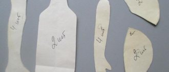
Later bought at a flea market, a copper rod with a cross section of 16mm. from which the turner turned future electrodes at my request. Attached is a drawing of the electrodes.
Well, while the turner is creating, I am improving the transformer and all the components that serve it. The circuit included an on/off automatic switch, a fan for blowing the transformer, a magnetic starter, a micro switch controlling the starter and a pair of light bulbs to indicate the presence of the network and the operation of the transformer. For those who are especially curious and want to know how it’s all connected, I’m attaching a circuit diagram.
The circuit I used provides for the operation of a micro switch from a 220V network, this is fraught with electric shock, in order to avoid such cases it is necessary to introduce a low-voltage relay into the circuit, which I will definitely do in subsequent modifications
This is how I placed the nodes inside the device.
The housing cover was made from the same microwave, the air intake fins (those on the side) are original, and the holes on the back wall are made in the form of a tube sheet, calculated in the Compass 3D program. I printed it out and transferred it to metal, drilled it and removed the burrs.
Well, I still have to work with the pliers to ensure the required force is pressed, I’m thinking of making an eccentric, because the lever system will take up a lot of space.
This is how the electrodes turned out.
In use: metal less than 0.8mm thick. It welds well, but in order to cope with thicker metal, I think it is necessary to modify the pliers and perhaps make the angle on the electrodes sharper. I think the information presented above is quite enough for do-it-yourselfers like me who want to repeat this design.
Homemade author: Vadim Orekhov.
Popular homemade products on our website
- Microwave spot welding
- DIY spot welding spotter (26 photos)
- Do-it-yourself spot welding: diagram and description of homemade product
- Do-it-yourself spot welding: diagram, photo and description
- Contact welding from the microwave
- Do-it-yourself resistance welding
- Microwave welding machine
- Homemade contact welding and spotter from two...
- DIY Hot Rod
- DIY grain crusher
- DIY self-leveling floor
- DIY pallet house
Electrical part
A microwave oven emits magnetic waves of millimeter and centimeter lengths. They warm up the objects they pass through well, but are completely unsuitable for welding, since it is impossible to create an electric arc on the electrode. Replacing the winding allows you to supply a large direct current to the spotter electrode . It is enough to install equipment with household power in the straightening garage.
The operating principle of a microwave spotter is based on resistance spot welding technology. The transformer produces a large current with a voltage of 12V. The impulse lasts for a short period of time. The spotter electrode should only stick to the body steel without burning through the thin sheet. This is a rare case when sticking of the electrode does not interfere with the welding process, but is specially created.
The current is changed by creating windings. The step-by-step plan for the main alterations is simple.
- Disassemble the microwave oven. Remove the microwave unit with coils from it.
- Remove the windings. The easiest way is to cut off the wires on both sides of the case and remove the bundles inside.
- Wind the primary winding with wire 2.5 mm2 in cross section, 200 - 210 turns.
- The secondary winding of the spotter is only 7 turns, the wire has a cross-section of 55 mm2. You can use a single-core cable of this diameter.
The second circuit of the spotter should produce a voltage of 12 V. The output current to the electrode is 5000 - 7000 A. The pulse duration is up to 0.5 seconds.
Head of the site for the production of welding equipment KZESO Podgorbunsky D.S.: “The wire is wound smoothly, with the turns adjacent to each other. To secure the winding in working condition and extend its service life, the finished spotter coil is impregnated with varnish. The best option is Varnish FL-98. It is manufactured by domestic manufacturers in accordance with GOST 12294-66. Produced in containers for industrial enterprises of 50 and 70 kg. For consumers, 5 liters in a canister. It can be replaced with varnishes of the ML, GF and PF series. The varnish is heated in a container to 120⁰C, and a clean, grease-free winding is carefully lowered into it. Cardboard, used as insulators between the coils and the walls of the case, is impregnated with the same varnish and dried. Impregnation with varnish significantly increases the service life of the spotter.”
Three simple DIY spotter assembly schemes
Spotter is the common name for a single-sided spot welding machine designed for repairing car body parts.
Its design is quite simple, so any home craftsman with experience working with electrical devices can make a spotter with his own hands. The only thing that cannot be mistaken is the choice of power, calculation of the current strength and the number of windings.
Craftsmen use various devices as power sources, but not all of them are capable of providing optimal operating conditions.
For example, a homemade microwave spotter, even when using several transformers from this household appliance, is generally suitable for warming up. If there is no sufficiently powerful electrical network at the repair site, devices with an autonomous source are used, consisting of a battery and a voltage interruption circuit.
Such devices have one significant drawback - limited operating time. When assembling a homemade spotter, you can use various control systems: from a simple button with a relay to an inverter source.
In the latter case, the current supplied from the inverter to the welding site is regulated with high accuracy both in duration and in pulse amplitude.
Is it possible to make a spotter with factory specifications?
If you correctly calculate the parameters, select the appropriate components and make high-quality not only the power supply, but also the tool accessories, then a homemade spotter in its functionality will be no different from its factory counterpart.
If you have some amateur radio skills, it is easy to make the power supply and the necessary wires yourself.
As a welding gun, you can use any product of a suitable shape, the design of which would allow you to strengthen the threaded contacts at its ends and would be convenient to use.
The gun and reverse hammer will require several parts, which are best turned on a lathe. Some electrode tips can be made with your own hands using ordinary plumbing tools, but some are still better to order or purchase ready-made.
In order to operate a home-made device, additional devices may be required (pullers, combs, rods), which can also be made independently. Consumables for a spotter (welding washers, studs, corrugated wire, carbon electrodes, etc.) are inexpensive and are freely sold in specialized stores.
Main components for assembly
To assemble and test a homemade spotter, you need the following components and consumables:
- Frame. Sheet metal box structure with front and back panels. Ventilation holes and a ground terminal are required.
- Power supply. In its simplest form, it is a do-it-yourself transformer with a circuit breaker in the primary circuit.
- Power cables. The welding cable must have a terminal for connection to power and a threaded contact for connection to the gun, and the ground cable must have a terminal and contact pad for welding connection to the body part.
- Control circuit. The minimum version includes a switch button on the gun, an input voltage cut-off relay, control wires and a control circuit power supply.
- Welding gun. At one end there is a contact threaded connection for connecting electrodes and adapters, and at the other there is a socket for connecting a welding cable.
- Equipment. The basic version includes electrodes for washers and pins, a return hammer and an adapter for connecting a carbon electrode.
Provided that all components are made without deviations and nothing has to be adjusted or altered, for DIY assembly you will need ordinary plumbing and power tools. Measuring instruments you may need are a tape measure, a caliper and a multimeter.
Spotter housing and final assembly
In general, the assembly of a homemade spotter is completed by placing its main elements in the housing and bringing the terminals and controls to the front panel. The housing can be ordered according to a drawing or simply a sketch, or (if possible) manufactured locally. Sometimes craftsmen begin to operate a spotter, the parts and wires of which are simply laid out on a workbench or even on the floor. This option is only suitable for debugging and selecting parameters; such an electrical installation cannot be used in constant mode. Since there are various options for making spotters with your own hands, their body layouts can also be different. For example, if a welding transformer is intended for use outdoors, then in this case the device may take the form of a stable base with a transformer, a terminal block and a separate control system housing.
In other cases, housing options may be different, but the control system elements must always be reliably protected from external influences.
Battery based
A battery powered spotter is suitable for applications where mains power is insufficient, unstable or non-existent and where body work is limited. Typically, this situation arises during body repair of a personal car in a garage cooperative or at a summer cottage. The body of such a homemade spotter may consist of a small support frame for installing the battery, to which a terminal block and a relay that controls shutdown are attached. If this is a one-time job, then you can do without a housing at all by attaching the relay to the battery with a clamp.
Based on a household microwave
To make a spotter with your own hands, a transformer from a microwave is also suitable. In this case, the only limitation is its power, since most microwave ovens are designed to consume less than 1 kW. To solve this problem, you can use two or three transformers connected in parallel. The advantage of such a power source is the small size of the transformers used, which can be placed in a row inside a small-sized housing. The result is a fairly compact and mobile spotter. The only thing you have to worry about is cooling the internal space of such a device.
How to make a spotter from a microwave transformer with your own hands
Videos about a DIY microwave spotter demonstrate that converting a high-voltage converter for a home welding machine is quite simple. The detailed algorithm looks like this:
- Remove the cover from an old but working microwave oven by unscrewing the screws holding it in place and dismantle the required element. To do this, you must first disconnect the terminals connecting the part to the remaining parts of the microwave and remove the fastening screws. Before starting work, disconnect the microwave oven from the network.
- The transformer is removed from the microwave oven body. Since assembly of the spotter requires a voltage-reducing element, the secondary high-voltage winding will have to be removed. To do this, the electric transformer from the microwave oven is securely fixed in a vice and unnecessary coils of copper wire are cut off on both sides using a hacksaw. The remains of the secondary winding inside the body of the part are first drilled out with a drill, and then knocked out using a pin and a hammer. When removing old transformer windings from a microwave oven, it is important not to damage the primary turns.
- The prepared element needs to be rewound in accordance with the new goals. To do this, take a copper wire with a diameter of at least 16 mm and make 2-3 turns, this is quite enough to obtain a current of sufficient power. When rewinding a transformer from a microwave, the turns are placed closer to each other
- The transformer and controls must be placed in a reliable housing. The easiest way is to take a metal box from a microwave oven. The converted element is placed in the center to balance the structure; according to the diagram, a resistor, a thyristor and a diode bridge are installed nearby, converting the current from direct to alternating. The spotter components must be secured to a dielectric material that prevents interference.
Finally, terminals for connecting cables and the main elements for welding are displayed on the front control panel of a homemade spotter. It is necessary to connect power wires, a return hammer and a working gun to the unit.
Important! A spotter based on a microwave oven transformer is mobile and quite lightweight. Therefore, it makes sense to attach handles to its body for convenient carrying of the device.
Creating a Corpus
Homemade spot welding machines have simple housings. Most are made exclusively from wood. This requires:
- base (board 10-20 mm);
- side walls;
- corners and screws;
- top cover.
It is necessary to make a hole in the side wall for the outlet of the power wire. The front part is not closed, since working pliers and cables are routed through it. It is worth screwing a thick tape into the top cover to carry the device.
There are no ventilation holes, but a computer cooler is inserted into the back wall of the device, which provides the necessary cooling. The absence of a front wall where the working jaws are removed, and a fan in the rear, cool the air and parts inside well.
Schemes of homemade spot welding machines and videos on how to create them on the Internet help to make a device that serves as a good help in the household and is much more economical in cost than store-bought versions.
https://www.youtube.com/watch?v=tf5-uJ_pn-o
What is resistance welding
Resistance spot welding is a method of joining workpieces in the form of rolled metal sheets or welding various piece products to structures: bolts, washers, rivets and much more. This resistance welding technology is most widely used in industries such as automotive, aircraft and instrument making.
Owning a spot welding machine provides a number of advantages and additional capabilities, namely:
- the ability to weld products from sheet metal with small thickness;
- ability to weld low-melting metals;
- neat and durable weld seam.
The main advantage of resistance spot welding is that you can learn to work on it yourself, having only a basic level of knowledge. To do this, you need to practice a little and you will be able to achieve high performance when working on such a device, with a relatively low cost of consumables and electricity.
How to make a spotter from two transformers from a microwave with your own hands
One transformer from a microwave oven allows you to assemble a working spotter with your own hands, but the power of the device will be insignificant. Therefore, two current converters are often used at once. Both can be taken from old microwave ovens, if you have them on hand.
A DIY microwave spotter step by step with two electrical transformers is not much more complicated in terms of assembly:
- Current converters for a homemade welding machine are being redesigned for new purposes. The secondary winding on both elements taken from the microwave oven is completely removed and several turns of a conductive wire with a cross-section of 50 mm2 are wound.
When rewinding transformers, it is important not to forget to lay insulation between the primary and secondary turns - According to the circuit diagram of a do-it-yourself spotter, electrical transformers removed from the microwave oven are installed in a housing or on an open panel next to each other.
Space is left between the transformers so that they do not touch and do not overheat. - A diode bridge and a variable resistor are placed in the housing or on the platform. The latter has to pass through itself a current with minimal values, so its power does not play a special role. Also, in accordance with the selected circuit, an electrolytic capacitor with an operating voltage of 25V is connected to the system.
You need to provide holes in the walls of the case for cooling or leave the lid open
Terminals for connecting the electrode and ground cable are placed in the front part of the assembled unit. You can also install additional elements - an ammeter for monitoring welding current, network indicators and regulators.
Important! When assembling a spotter with two transformers, it is necessary to connect their secondary windings in parallel. This is what will allow you to double the output power while leaving the voltage the same.