It is the simplest design for flashing PIC family controllers. The undeniable advantages - simplicity, compactness, power supply without an external source of this classic programmer circuit - made it very popular among radio amateurs, especially since the circuit is already 5 years old, and during this time it has established itself as a simple and reliable tool for working with microcontrollers.
Schematic diagram of the programmer for pic controllers:
No power is required for the circuit itself, because this is done by the COM port of the computer, through which the microcontroller firmware is controlled. For low-voltage programming mode, 5V is sufficient, but all options for change (fuses) may not be available. The COM-9 port connector was mounted directly on the PIC programmer circuit board - it turned out very convenient.
You can plug the board directly into the port without any extra cords. tested on various computers and when programming MKs of the 12F, 16F and 18F series, showed high quality firmware. The proposed circuit allows programming PIC12F509, PIC16F84A, PIC16F628 microcontrollers. For example, recently, using the proposed programmer, a microcontroller for .
For programming, WinPic800 is used - one of the best programs for programming PIC controllers. The program allows you to perform operations for microcontrollers of the PIC family: reading, writing, erasing, checking FLASH and EEPROM memory and setting configuration bits.
PIC microcontrollers have earned fame due to their unpretentiousness and quality of operation, as well as versatility in use. But what can a microcontroller do without the ability to write new programs onto it? Without a programmer, this is nothing more than a piece of amazingly shaped hardware. The PIC programmer itself can be of two types: either home-made or factory-made.
Using a programmer from Microchip
You can find many tutorials on its use that will help you understand all sorts of aspects of its use. If we consider not only a PIC programmer purchased second-hand, but purchased from an official representative, then we can also notice the quality of support provided with it. So, in addition there are training materials on use, licensed development environments, as well as a demo board, which is designed to work with low-pin microcontrollers. In addition to all this, there are utilities that will make working with the mechanism more enjoyable and will help monitor the process of programming and debugging the microcontroller. A utility is also supplied to stimulate the operation of the MK.
Manually assembled programmers
And now, perhaps, the most interesting thing is the PIC controller programmers, which are assembled manually. This option is used by those who do not have money or simply do not want to spend it. If you purchase from an official representative, you can count on the fact that if the device turns out to be of poor quality, you can return it and get a new one in exchange. And when purchasing “from hand” or using bulletin boards, in case of poor-quality soldering or mechanical damage, you cannot count on reimbursement of expenses and receiving a high-quality programmer. Now let's move on to the hand-assembled electronics.
The PIC programmer can be designed for specific models or be universal (for all or almost all models). They are assembled on microcircuits that can convert signals from the RS-232 port into a signal that will allow programming the MK. You need to remember that when you assemble a design given by someone, the PIC programmer, the circuit and the result must match one to one. Even small deviations are undesirable. This remark applies to beginners in electronics; people with experience and practice can improve almost any circuit if there is room for improvement.
It’s also worth saying a word about the software package that is provided by the USB programmer for PIC, assembled with your own hands. The fact is that assembling the programmer itself according to one of the many schemes presented on the world wide web is not enough. You also need software that will allow the computer to flash the microcontroller with its help. Icprog, WinPic800 and many other programs are often used as such. If the author of the programmer circuit himself did not indicate the software with which his creation can do its job, then you will have to find out yourself by brute force. The same applies to those who assemble their own circuits. You can write a program for MK yourself, but this is real aerobatics.
Which microcontrollers are supported and can be flashed with software
As mentioned above, this programmer can work with at least 98 models. As you can see from the schematic drawings and boards, it is designed for those MKs that have 8, 14, 18, 28 and 40 pins. This should be enough for a wide variety of experiments and the construction of a wide variety of mechanisms that can only be done within the modest budget of the average citizen. We can be confident that a home-made programmer will be able to satisfy the most demanding radio amateurs - provided that it is made with high quality.
With the development of computer technology, each time there are fewer and fewer computers equipped with COM and LPT ports. This, in turn, causes difficulties, in particular for radio amateurs, associated with pairing microcontroller programming tools with a personal computer.
This article describes a USB programmer for AVR microcontrollers, which you can assemble yourself. It is built on an Atmega8 microcontroller and is capable of operating from a computer’s USB connector. This programmer is compatible with STK500 v2.
Universal programmers that are suitable not only for RIS
If a person is interested in programming microcontrollers, then it is unlikely that he will constantly use only one type. For those who do not want to buy separate programmers for different types of microcontrollers from different manufacturers, universal devices have been developed that can program microcontrollers from several companies. Since there are quite a lot of companies producing them, it’s worth choosing a couple and talking about the programmers for them. The choice fell on the giants of the microcontroller market: PIC and AVR.
The universal PIC and AVR programmer is equipment whose peculiarity lies in its versatility and the ability to change the operation thanks to the program without making changes to the hardware component. Thanks to this property, such devices easily work with microcontrollers that were released for sale after the release of the programmer. Considering that the architecture will not change significantly in the near future, they will be suitable for use for a long time. Additional pleasant properties of factory programmers include:
- Significant hardware restrictions on the number of programmable microcircuits, which will allow programming not one, but several pieces of electronics at once.
- Possibility of programming microcontrollers and circuits based on various technologies (NVRAM, NAND Flash and others).
- Relatively short programming time. Depending on the programmer model and the complexity of the programmed code, it may take from 20 to 400 seconds.
Paid versus homemade
Separately, we need to talk about store-bought and homemade programmers. The fact is that these devices are not very simple and require certain operating skills, soldering practice and the ability to handle iron. When working with a programmer purchased from the manufacturer or its dealer, you can be sure that the program will be recorded on the device and nothing will burn out. And if malfunctions are detected at the very beginning of the operating period, you can return it and receive a working device in return.
But with homemade programmers it’s always a little more complicated. The fact is that even if they were tested, then, as a rule, in a very narrow range of the equipment used, so the likelihood that something will go wrong is high. But even if the circuit itself is fully operational, one cannot discount the possibility that the person who assembled the circuit will make a mistake, solder something wrong, and as a result there will be dire consequences, at least for the programmer. Although, given how microcontrollers like to burn out, it won’t be the only one that will be damaged. When soldering your board, in order to avoid negative consequences, before assembling the mechanism, you should check the functionality of all elements that will be used in the board using special devices.
Features of practical use
Separately, it is worth touching on the topic of practical use. As a rule, programmers are connected to USB ports, but there are also variations that work using the same wires as the hard drive. And to use them you will have to remove the computer cover, sort out the wires, and the connection process itself is not very convenient. But the second type is more versatile and powerful, thanks to it the firmware speed is faster than when connected via USB. Using the second option does not always seem to be such a convenient and comfortable solution as with USB, because before using it you need to do a number of operations: take out the case, open it, find the necessary wire. You don’t have to worry about possible problems from overheating or power surges when working with factory models, since they usually have special protection.
Drivers
Initially, you should select the software. Depending on the circuit, the programmer can be tailored either for one microcontroller or for a large number of them. The one that will be considered further is designed for approximately 98 programmers from the 12th to 18th families. For those who like the assembly option, it should be clarified that the IC-PROG program was used as driver software. You can try to work with another one, but at your own peril and risk. This information is for those who want to create a programmer for AVR with their own hands. Next it will be indicated for which families of RIS microcontrollers it is designed. If you want to make an AVR programmer with your own hands or some other type of MK, then you can always try.
Working with microcontrollers
What is necessary for all programmers with microcontrollers to work? The fact is that, although the programmers themselves are independent circuits, they transmit computer signals in a certain sequence. And the problem of how to explain to the computer what exactly needs to be sent is solved by the programmer software.
There are quite a lot of different programs available in the public domain that are aimed at working with programmers, both home-made and factory-made. But if it is manufactured by a little-known company, was made according to the design of another electronics enthusiast, or by the person reading these lines himself, then the software may not be found. In this case, you can use a search of all available programming utilities, and if none of them work (if you are sure that the programmer works well), then you need to either take/make another PIC programmer, or write your own program, which is a very high level of pilotage.
Microcontroller firmware process
The process of flashing the microcontroller with data can be considered a continuation of the previous list:
- Make the necessary settings for the program to work.
- Install the microcontroller into the programmer as indicated in the diagram. It’s better to make sure once again that everything is as it should be than to go for a new MK.
- Connect power.
- Launch the selected software (for this programmer we again recommend IC-Prog).
- In the drop-down menu at the top right, select which microcontroller you want to flash.
- Select the prepared file for programming. To do this, follow the path “File” - “Open file”. Look, don’t confuse it with “Open data file”, this is completely different; you won’t be able to flash the microcontroller using the second button.
- Click on the “Start programming the chip” button. The approximate time after which it will be programmed is up to 2 minutes. The programming process cannot be interrupted, as this could damage the microcontroller.
- And as a little control, click on the “Compare chip with buffer” button.
It’s not very difficult, but this sequence of actions allows you to get a high-quality, self-made programmer for various types of RIS microcontrollers.
Possible problems
Alas, even the most ideal technology is not without possible problems, which, no, no, will arise. For improved understanding, it is necessary to make a list. Some of these problems can be corrected manually with a detailed inspection of the programmer, while others can only be checked if you have the necessary testing equipment. In this case, if the PIC microcontroller programmer is factory-made, it is unlikely to be repaired. Although you can try to find possible causes of failures:
- Poor quality soldering of programmer elements.
- Lack of drivers to work with the device.
- Damage inside the programmer or wires inside the computer/USB.
Experiments with microcontrollers
So, everything is there. How to start working with equipment, how to start flashing a microcontroller with a programmer?
- Connect external power, connect all equipment.
- Initially, an environment is needed with the help of which everything will be done.
- Create the required project, select the microcontroller configuration.
- Prepare a file containing all the necessary code.
- Connect to the programmer.
- When everything is ready, you can flash the microcontroller.
Above, only a general diagram was written, which allows you to understand how the process occurs. It may differ slightly for individual development environments, and more detailed information about them can be found in the instructions.
I would like to write a separate appeal to those who are just starting to use programmers. Remember that, no matter how basic some steps may seem, you must always adhere to them so that the equipment can work normally and adequately and perform the tasks you set. Good luck in electronics!
Circuits using microcontrollers are gaining quite a lot of popularity on the Internet. A microcontroller is a special chip that, in essence, is a small computer with its own input/output ports and memory. Thanks to a microcontroller, you can create very functional circuits with a minimum of passive components, for example, electronic clocks, players, various LED effects, and automation devices.
In order for the microcircuit to begin performing any functions, it needs to be flashed, i.e. load the firmware code into its memory. This can be done using a special device called a programmer. The programmer connects the computer on which the firmware file is located with the microcontroller being flashed. It is worth mentioning that there are microcontrollers of the AVR family, for example, Atmega8, Attiny13, and pic series, for example PIC12F675, PIC16F676. The Pic series belongs to Microchip, and the AVR series belongs to Atmel, so the firmware methods for PIC and AVR are different. In this article we will look at the process of creating an Extra-pic programmer, with which you can flash a pic series microcontroller. The advantages of this particular programmer include the simplicity of its circuitry, reliability of operation, and versatility, because it supports all common microcontrollers. The computer is also supported by the most common firmware programs, such as Ic-prog, WinPic800, PonyProg, PICPgm.
Programming Atmega8 via LPT port of a computer
The fastest and cheapest way to program Atmega8 is to use an LPT programmer for AVR. A similar diagram is shown below.
The microcontroller is powered by a simple 78L05 voltage regulator. You can use the UniProf program as a programming shell.
When you first turn on the program and when the controller is not connected, by pressing the “LPTpins” button, you need to configure the LPT port pins as follows:
When UniProf starts, it automatically determines the type of microcontroller. We load the Atmega8_USB_prog.hex firmware into the UniProf memory and reject the connection of the EEPROM file.
We set the fuses as follows (for the UniProF program) by pressing the “FUSE” button:
To remember the settings, press all three “Write” buttons. Then by clicking on “Erase” we first clear the memory of the microcontroller being flashed. After this, click on “Prog” and wait for the firmware to complete.
Materials
List of parts required to assemble the programmer:
- Stabilizer 78L05 – 2 pcs.
- Stabilizer 78L12 – 1 pc.
- LED 3 V. green – 1 pc.
- LED 3 V. red – 1 pc.
- Diode 1N4007 – 1 pc.
- Diode 1N4148 – 2 pcs.
- Resistor 0.125 W 4.7 kOhm – 2 pcs.
- Resistor 0.125 W 1 kOhm – 6 pcs.
- Capacitor 10 uF 16V – 4 pcs.
- Capacitor 220 uF 25V – 1 pc.
- Capacitor 100 nF – 3 pcs.
- Transistor KT3102 – 1 pc.
- Transistor KT502 – 1 pc.
- Chip MAX232 – 1 pc.
- Chip KR1533LA3 – 1 pc.
- Power connector – 1 pc.
- Female COM port connector - 1 pc.
- DIP40 socket – 1 pc.
- DIP8 socket – 2 pcs.
- DIP14 socket – 1 pc.
- DIP16 socket – 1 pc.
- DIP18 socket – 1 pc.
- DIP28 socket – 1 pc.
In addition, you need a soldering iron and the ability to use it.
Programmer assembly
First of all, jumpers are soldered onto the printed circuit board, then resistors, diodes.
Lastly, you need to solder the sockets and power connectors and COM port. Because There are a lot of sockets on the printed circuit board for flashed microcontrollers, but not all of their pins are used; you can use this trick and remove unused contacts from the sockets. At the same time, less time will be spent on soldering and inserting a microcircuit into such a socket will be much easier. The COM port connector (called DB-9) has two pins that must be “stuck” into the board. In order not to drill extra holes on the board for them, you can unscrew the two screws under the sides of the connector, and the pins will fall off, as will the metal edging of the connector. After soldering all the parts, the board must be washed from flux, and the adjacent contacts must be ringed to see if there are any short circuits. Make sure that there are no microcircuits in the sockets (you need to remove both MAX232 and KR1533LA3), connect the power. Check if there is a voltage of 5 volts at the outputs of the stabilizers. If everything is fine, you can install the MAX232 and KR1533LA3 microcircuits, the programmer is ready for use. The supply voltage of the circuit is 15-24 volts. The programmer board contains 4 sockets for microcontrollers and one for flashing memory chips. Before installing the microcontroller to be flashed on the board, you need to check whether its pinout matches the pinout on the programmer board. The programmer can be connected to the computer's COM port directly or via an extension cable. Happy build!
One day I decided to assemble a simple LC meter for pic16f628a and naturally it had to be flashed with something. I used to have a computer with a physical COM port, but now I only have USB and a pci-lpt-2com board. To begin with, I assembled a simple JDM programmer, but as it turned out, it did not want to work with either the pci-lpt-com board or the usb-com adapter (low voltage of RS-232 signals). Then I rushed to look for usb pic programmers, but there, as it turned out, everything was limited to the use of expensive pic18f2550/4550, which I naturally didn’t have, and it’s a pity to use such expensive MKs if I very rarely do anything at peaks (I prefer av- Yes, flashing them is not a problem, they are much cheaper, and it seems to me that it is easier to write programs on them). After delving for a long time on the Internet in one of the many articles about the EXTRA-PIC programmer and its various variants, one of the authors wrote that extrapic works with any com ports and even a usb-com adapter.
The circuit of this programmer uses a max232 logic level converter.
I thought that if you use a usb adapter, it would be very stupid to convert the usb to usart TTL, TTL to RS232, RS232 back to TTL levels twice, if you can just take the TTL signals of the RS232 port from the usb-usart converter chip.
So I did. I took the CH340G chip (which has all 8 com port signals) and connected it instead of max232. And this is what happened.
In my circuit there is a jumper jp1, which is not in the extra peak, I installed it because I didn’t know how the TX output would behave at the TTL level, so I made it possible to invert it on the remaining free NAND element and, as it turned out, it was right there is a logical one at the TX pin, and therefore there is 12 volts at the VPP pin when turned on, but nothing will happen during programming (although you can invert TX in software).
After assembling the board, it was time for testing. And here came the main disappointment. The programmer was identified immediately (with the ic-prog program) and started working, but very slowly! In principle - as expected. Then in the com port settings I set the maximum speed (128 kilobaud) and began testing all the found programs for JDM. As a result, PicPgm turned out to be the fastest. My pic16f628a was fully flashed (hex, eeprom and config) plus verification for about 4-6 minutes (reading is slower than writing). IcProg also works, but slower. There were no programming errors. I also tried to flash eeprom 24c08, the result is the same - everything sews, but very slowly.
Conclusions: the programmer is quite simple, it does not contain expensive parts (CH340 - $0.3-0.5, k1533la3 can generally be found among radio junk), works on any computer, laptop (and you can even use tablets on Windows 8/10). Cons: it is very slow. It also requires external power for the VPP signal. As a result, it seemed to me that for infrequent flashing of peaks, this is an easy to repeat and inexpensive option for those who do not have an ancient computer with the necessary ports at hand.
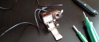
Here is a photo of the finished device:
As the song says, “I made him out of what was.” The set of parts is very diverse: both SMD and DIP.
For those who dare to repeat the circuit, almost any one will be suitable as a usb-uart converter (ft232, pl2303, cp2101, etc.), instead of k1533la3, k555 will be suitable, I think even k155 series or a foreign analogue 74als00, it may even work with logical NOT elements of the type k1533ln1. I am attaching my own printed circuit board, but anyone can redraw the wiring there for the elements that were available.
List of radioelements
| Designation | Type | Denomination | Quantity | Note | Shop | My notepad |
| IC1 | Chip | CH340G | 1 | To notepad | ||
| IC2 | Chip | K1533LA3 | 1 | To notepad | ||
| VR1 | Linear regulator | LM7812 | 1 | To notepad | ||
| VR2 | Linear regulator | LM7805 | 1 | To notepad | ||
| VT1 | Bipolar transistor | KT502E | 1 | To notepad | ||
| VT2 | Bipolar transistor | KT3102E | 1 | To notepad | ||
| VD1-VD3 | Rectifier diode | 1N4148 | 2 | To notepad | ||
| C1, C2, C5-C7 | Capacitor | 100 nF | 5 | To notepad | ||
| C3, C4 | Capacitor | 22 pF | 2 | To notepad | ||
| HL1-HL4 | Light-emitting diode | Any | 4 | To notepad | ||
| R1, R3, R4 | Resistor | 1 kOhm | 3 |
1. PROGRAMMER FOR PIC CONTROLLERS
I hope that my article will help some radio amateurs cross the threshold from digital technology to microcontrollers. There are many programmers on the Internet and in amateur radio magazines: from the simplest to the most sophisticated. Mine is not very complicated, but reliable.
The first version of the programmer is designed for programming 18 and 28 “pin” PIC controllers. The programmer is based on a diagram from Radio No. 10 magazine for 2007. But selecting the C7 capacitor and experimenting with different versions of ICprog, PonyProg, WinPic and read-write speeds did not give the desired result: successful programming was achieved every other time. And this continued until the +5V power supply of the programmable microcircuit was made separately, and not after a 12-volt stabilizer. The result is the following diagram.
Fearing failures, I drew the signet so that the board was inserted directly into the Com port, which is not very easy due to all kinds of “laces” and the short distance to the case. The signet turned out to be of irregular shape, but it is inserted into the COM port normally and programs without errors.
Over time, I made an extension cord about 1 meter long. Now the programmer lies next to the monitor and is connected to the COM port. It works fine: microcontrollers PIC16F84A, PIC16F628A, PIC16F873A have been programmed many times.
Please note: the Max chip and LEDs are installed on the side of the printed conductors. The sockets are ZIF-28, one of them is used for 18-pin PIC. The panels bear the marks of the first legs and the numbers “18” and “28”. A 220 15 volt, 4 watt transformer is installed in the adapter plug housing. You need to plug it into the outlet after installing the microcontroller in the socket. NPN transistors are low-power, high-frequency (300 MHz) in a to-92 package.
I didn’t install the XP connector for a while, and then it turned out that it wasn’t really needed. I had to somehow program the soldered MK, so I inserted the wires directly into the ZIF and fixed it. Reprogramming was successful.
I work with ICprog and WinPic-800 programs.
The IC-prog 1.05D program has the following programmer settings:
- Programmer – JDM Programmer
- Port –Com1
- Direct access to ports.
- Inversion: input, output and clocking (check the boxes).
In WinPic-800 –v.3.64f everything is identical, you just need to install the “bird” in using MCLR.
You can download these programs freely and freely on the Internet. But to make life easier, I will try to do everything necessary. I just remembered how many “unnecessary things” I myself downloaded from the Internet, and how much time I spent sorting it all out.
- Programmer circuit board
- WinPic-800 program ( )
- Program IC-Prog()
- Article on IC-Prog.
2. PROGRAMMER-2 FOR PIC CONTROLLERS
Over time, the need arose to program 14 and 40 “pin” peaks. I decided to make a programmer for the entire average family of PICs. The scheme is the same, only two panels have been added. All this is housed in a housing from a former multimeter.
A correction was made to the printed circuit board on February 13, 2014: from the 5th pin of the RS232 connector, the track goes to the power supply minus (and on the previous one, to the 6th leg of the MAX chip). New signet in “programer2-2”.
You can save one Kren. Those. connect the entire circuit from one 5-volt stabilizer. Do not install VR3 and C9, but install a jumper (indicated by a dotted line in the diagram). But I haven’t soldered Krenka yet. Programmed PIC16F676, 628A, 84A and 873A many times. But I haven't tried 877 yet.
Some capacitors are installed on the side of the printed conductors. The rollers are located in a horizontal position. In order not to lay conductors, I installed C7 - 2 pcs and R12 - 3 pcs.
Very important: the housing of the RS232 connector must be connected to the power supply minus.
The power supply (15 V) and programs are used the same as in the first option.