How many people remember floppy disks? History buried flexible media back in the 90s. The only thing left from them is the design of the “Save” icon. Floppy disks could not keep up with technology - the volume of programs and data was rapidly increasing. The 2.88 MB of data that fit on standard 3.5-inch floppy disks was no longer enough. Consumers have switched to optical media. Decades later, users forgot about floppy disks, and floppy drives became something like dishes in a sideboard. But not for Polish engineer Pawel Zadrozniak. Back in 2011, he assembled a device consisting of two floppy drives and named it appropriately - “Floppotron”. On it he “played” the Imperial March. The video went viral and Pavel moved on.
In 2016, the engineer presented the world with the second version of his musical instrument. Its equipment has become more impressive: 64 floppy drives, 8 hard drives and 2 scanners. On his YouTube channel, Pavel performed more than a hundred popular songs.
He inspired many people. Some assembled simple floptrons from several drives, while others tried to extract sounds from devices that were more non-standard for floptrons. For example, the Device Orchestra channel creates melodies using payment terminals, electric toothbrushes and even steam cleaners.
Floppotron v2 is the brainchild of Polish engineer Pavel Zadrozniak
Floppy Drive Control
The drive has two connectors - one for power (“mini-molex”) and the second for control (FDD). The drive is powered immediately from 5V and 12V. An excellent solution would be to use a computer power supply. When working with it, be sure to short the PS_ON pin to the COM pin to turn it on. However, any other power supply with the same voltages will do. The main thing is that there is enough output amperage.
The mini-molex connector has two ground pins in the middle and 12V and 5V pins on the sides. The 12V contact is located on the left and often there is a “key” on its side that prevents the plug from being connected to the wrong side.
Although the FDD connector has an intimidating number of pins, you only need two from there - 18 and 20.
Pin 18 is called “Stepper Direction”, and it sets the direction of movement of the write head. Pin 20 is called “Step Pulse” and it directly “pushes” the stepper motor.
In addition, you need to allow the engine to run. To do this, you need to short-circuit pin 12 of the “Drive Select B” connector to ground. This can be done either by a jumper (jumper) between this contact and the bottom one (11 - ground), or by directly connecting pin 12 to the ground wire. Barbarians can simply bend this contact down so that it comes into contact with the lower contact.
Connection diagram to a floppy drive
Alternatives
It’s a bit difficult to find analogues and alternatives.
They are more intended for something else. First, there's KryoFlux.
This is a converter for connecting conventional drives to a USB port. And, first of all, it is intended for saving images of floppy disks (and writing them back to floppy disks). The advantage is that it works with almost all formats. The downside is that this is not a replacement for the disk drive as such. Well, it cannot be seen as a disk under Windows.
Secondly, there is the FC5025 USB 5.25″ floppy controller.
This is approximately the same KryoFlux, only the pipe is lower - it only works with 5.25″ floppy disks, and cannot write to floppy disks. some kind of adapter for 5.25
Thirdly, there is a CATWEASEL MK IV. PCI multicard.
True, it is rather theoretically there, production stopped somewhere in the 2000s and now you can no longer see it alive.
Fourth, USB drives.
But, as I already said, these are not alternatives, they all work in the other direction - connect the drive to a modern computer. Instead of making an old device happy with a modern flash drive.
Switching
For a simple floppy cartridge, in addition to the floppy drives themselves and the controller, you only need connecting wires. A total of 5 wires should go to the drive: 2 control, 12V, 5V and ground.
Connecting wires to the floppy drive
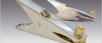
The return end of the control wires will connect to the Uno. The remaining wires (i.e., power buses) will need to be connected to the power supply. If there are not too many disk drives, an excellent solution would be to connect them via a terminal clamp. The wires from the drives will be screwed in on one side, the wires from the power supply on the other. In this case, it will always be possible to easily power new drives without unsoldering anything.
One way to connect power to floppy drives
Additional wires need to be taken from the 5V power bus and ground and connected to the pins of the Uno board.
Connecting wires with the Uno board
From an old floppy drive - a machine for straightening small drills
Once upon a time, I made a machine out of an old “Winchester” for straightening and sharpening small drills, but its minimum rotation speed is too high and usually when you are in a hurry, the drills overheat. I tried to somehow reduce the speed, but nothing good happened, so I left everything as it was, just forcing myself to take my time. And then recently my computer geek friends came and asked, “Look, can you make something useful out of this?” They began to dump a lot of three and a half inch disk drives onto the table ( Fig. 1 ). And for some reason, my first thought was: shouldn’t I try to assemble a new low-speed “edit”...
Fig.1
Without putting this matter off for a long time, we immediately remove the covers from several drives of different brands and look at what’s inside.
But inside everything is different, and for different models of the same brand, motor control can be assembled on one or two microcircuits ( Fig. 2 ).
Fig.2
We look at the details on the boards in more detail and give preference to the option with two microcircuits ( Fig. 3 ) - from the tracks and suitable wires it is clear that the right ALPS-R SD705A microcircuit (among other things) is responsible for the operation of the stepper motor for moving the read head, and the left LB11813 - only for the operation of the disk rotation motor.
Fig.3
It can also be seen that both microcircuits are connected by only two signal paths - pins 33 and 34 of the large microcircuit go to the 10th and 11th pins connected together and to the 12th pin of the LB11813, respectively.
To be honest, I’ve already had to deal with disk drives before and I already have some idea of the principle of their operation, therefore, having said for greater importance “now we’ll cut something here...”, I carefully cut both of these tracks ( Fig. 4 ).
Fig.4
We leave pin 12 of the LB11813 chip alone, and on the 10th and 11th we need to apply the CLK clock signal. Since its repetition frequency should be about 1 MHz, and the amplitude is standard for five-volt series microcircuits, we assemble a rectangular pulse generator on a K555LN1 microcircuit on a piece of textolite that comes to hand. We install a variable resistor to regulate the frequency and, in its middle position, adjust the output frequency to 1 MHz by selecting the capacitance of the capacitor. Then we connect the generator output to the terminals of LB11813 ( Fig. 5 ), solder the power buses of the disk drive and the generator and turn on the power supply. We hear the engine begin to rotate. This is good... By turning the variable resistor knob, we hear how the engine speed changes. And this is good…
Fig.5
The guests, joyful and inspired by the new prospects, rushed home, thinking as they went about how they could use this “miracle of technology,” and I returned to the diagram to see what needed to be left and what to remove, and how to improve it all in the building...
First, armed with a tester, a pencil and a piece of paper, I copied a circuit from the board ( Fig. 6 ). Here, the numbering of the elemental wiring related to the LB11813 microcircuit is left the same, i.e. the one that was on the board.
Fig.6
Then I looked at some technical specifications. The current consumed from a five-volt power supply at idle is 0.22 A, with an average “load” on the motor shaft it varies from 0.5 A to 0.7 A. Just before the rotation stops, the current reaches a value of 0.85 A. Heating temperature case of the LB11813 chip depends on the load, but in any case does not exceed 50-70 degrees.
The minimum generator frequency at which the engine is still rotating is about 0.45 MHz, the maximum is about 4.6 MHz.
Now I completely disassemble the drive, leaving only two boards connected by 4 colored wires - through them the LB11813 microcircuit controls the motor ( Fig. 7 ). The white eight-wire cable is also not needed - what was interesting on the board with the motor was either a choke or some other element, but very similar to a choke and most likely responsible for controlling the engine speed (i.e. performing the functions Hall sensor) - so you can unsolder it, everything works without it. The remaining conductors of the loop are the common wire, the supply voltage, and also the transmission of signals from the limit switches from the motor board (we solder them too).
Fig.7
Using a hot air gun, I “blow off” all the unnecessary elements from the large board and cut it off so that the mounting holes remain ( Fig. 8 ).
Fig.8
Frame.
I couldn’t find a ready-made one that was suitable in size, so I took a piece of 16mm chipboard, a thin plastic sheet and a piece of fiberglass from an old printed circuit board. I sawed a little, drilled and secured everything so that it did not “stick out” too much and did not take up much space on the table ( Fig. 9, Fig. 10, Fig. 11, Fig. 12 ).
Fig.9
Fig.10
Fig.11
Fig.12
I wired up the printed circuit board for the pulse generator, but haven’t etched it yet - I don’t want to wire up the “bad guy” for the sake of one or two small boards. In the meantime, I installed a prototype version into the case and glued it and the board with the motor drive microcircuit with hot glue. The printed circuit board file in the Sprint-Layout program format is located in the appendix to the article (the view is taken from the installation side of the parts - the drawing for LUT must be “mirrored”).
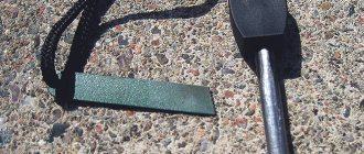
I did not cover the top of the case with any decorative panel - I left the screw heads exposed. The plastic from which the top cover is made turned out to be very successful - no adhesives from the “Moment” or BF series stick tightly to it, and it practically does not scratch or smudge. From the part that remained when cutting out the hole for the rotating surface of the engine, I cut out a ring, which I glued on top to this rotating surface. You can stick sandpaper rings onto this ring ( Fig. 13 ), which can be easily torn off if desired and there will be almost no glue residue left on the plastic surface of the ring. And what remains is scratched off with a fingernail.
Fig.13
As a power supply I used a pulse converter that produces 5V/1A from some old office equipment. The power cord is soldered directly into the circuit - this may not be very correct, but the power supply is never lost and then, when replacing it with a new one, you don’t have to figure out where the “plus” and where the “minus” are in the connector.”
There are no switches on the case, nor any indication of voltage supply. The speed control resistor motor is located on the side. Considering that over the past month I had to adjust the drills twice and once sharpen several broken ones of different diameters, and during this time there was never a need to reduce the speed, it turns out that it was possible not to make a smooth adjustment. Set the generator to 4 MHz and that’s it.
Of course, I checked the operation of the circuit with the motor from the hard drive - everything works the same, but with noticeably less power compared to control from the “native” controller. This is understandable - the HDD motor requires a higher supply voltage.
Out of academic interest, I looked at the waveforms in the motor power supply circuits. The figures below show the states on the “phases” U and V relative to the common wire at a clock frequency of 4.6 MHz ( Fig. 14 ), at 1 MHz ( Fig. 15 ) and on one of the “phases” and the pin designated on the boards as N (“neutral”, presumably) ( Fig. 16 ):
Fig.14
Fig.15
Fig.16
The signals were “recorded” through resistor dividers, so the levels do not correspond to the voltage scale readings, but since the division coefficients were the same and did not change, then the ratios of the levels relative to each other are correct. The time intervals are correct.
Andrey Goltsov, Iskitim
List of radioelements
| Designation | Type | Denomination | Quantity | Note | Shop | My notepad |
| List of additional elements | ||||||
| DD2 | Digital microcircuit | K555LN1 | 1 | Search in the Otron store | To notepad | |
| R1, R2 | Resistor | 470 Ohm | 2 | Search in the Otron store | To notepad | |
| R3 | Variable resistor | 470 Ohm | 1 | Search in the Otron store | To notepad | |
| R4 | Resistor | 10 kOhm | 1 | Search in the Otron store | To notepad | |
| C1 | Capacitor | 560 pF | 1 | Search in the Otron store | To notepad | |
| C2 | Electrolytic capacitor | 470 µF /6.3 V | 1 | Search in the Otron store | To notepad | |
| C3 | Capacitor | 100 nF | 1 | Search in the Otron store | To notepad | |
| Add all | ||||||
Attached files:
- Printed circuit board for drill leveling machine.rar (5 Kb)
Software part
If you decide to use Arduino, then first of all you need to install the Arduino IDE. It is also worth remembering that to work with Arduino clones you need to install the appropriate CH340G driver. You can read about all this in our article.
First, you should check the floppy drives for functionality. To do this, you can program the controller for some simple operations. For example:
int step = 2, direct = 3; // Control pins void setup() { pinMode(step, OUTPUT); pinMode(direct, OUTPUT); } void loop() { for(int i = 0; i < 80; i++){ //We run the read head along the entire length digitalWrite(step, HIGH); delay(10); digitalWrite(step, LOW); } digitalWrite(direct, !digitalRead(direct)); // Change the direction of movement }
This sketch should force the floppy drive connected to the first channel (2 and 3 pins) to move the read head evenly along the entire working length. As soon as the head reaches its end, the direction of movement is reversed and the cycle repeats.
After you have checked all the drives, you can start creating the software for the floattron or simply use a ready-made solution.
Moppy is an advanced floppy controller. It consists of two parts: the Arduino firmware that directly controls the floppy drives, and a computer program that sends commands to the controller via a USB cable.
Download the latest release of the program. The first archive contains a sketch for Arduino, the second - a program for a PC.
Note: The firmware requires the TimerOne library. It can be found in the Library Manager. To do this, open Sketch→Connect Library→Manage Libraries. Through the search bar of the opened Library Manager, you can find the required “TimerOne” library.
After installing the library, the firmware is ready for use. All that remains is to select the port to which the Uno is connected and flash it.
The first drive is connected to pins 2 and 3 of the board (“Stepper Direction” and “Step Pulse”, respectively). Next drive to 4 and 5, then to 6 and 7 and so on. Up to 9 drives can be connected to Uno (up to pin A5). After connecting all floppy drives, you can turn on the power supply.
Usage
The device comes with a disk containing several programs in Chinese, some advertising, documentation in Chinese and documentation in Chinese English. Almost everything is useless; I haven’t been able to use a single program. They showed a bunch of hieroglyphs, occasionally words about 2000 and XP flashed, but when I tried to do something with the flash drive, the message “access is impossible” popped up, even when running as an administrator.
Although there is also winhex with keygen - it is suggested to use it to create floppy disk images. And the attached instructions even mention that you need to use a keygen for registration.
Preparing a flash drive
The only useful information from the disk is that you can prepare the flash drive for use with the device by plugging it into the connector, holding down both buttons and turning on the power.
Then the flash drive will be formatted for use. The rest is practically useless. But if the device is already installed in the case, then pressing the buttons and plugging in the power at the same time can be inconvenient, so it’s easier to use a specially trained program. There is a program floating around the Internet from a European company (whose website no longer exists) designed to work with a similar emulator. Just in case, I’m posting it in one more place, more copies, useful and identical. After installation (preferably not in program files, but in some other folder - the program wants to write to its directory, although this behavior is configurable), you can run USB_Floppy_Manager_v1.40i and see the Batch Manage Tool program window. The programmers were somewhat inconsistent.
An attentive person will see something in common with the Chinese program. Yes, there is something. But here at least the letters are clear, unlike the Chinese.
On the left is a list of connected flash drives.
Before use, you need to right-click on the desired flash drive and format it. In this window, you can once again check that you are formatting the correct flash drive, select the size of the disks, whether to make them bootable during formatting (a minimum set of files is uploaded), and select how many floppy disks you want to have on the flash drive. In theory, the device itself supports up to a thousand (0-999), but this software only supports up to 100 (0-99). That's enough for me.
A formatted flash drive is perceived by a computer as a 1.44 megabyte USB drive. Well, depending on how much you format it (1.44, 1.2, 720k). You can write or read something there - it will then be clearly visible on the zero “floppy disk”. Although someone wrote that if you try to upload a large file there, other images may be damaged. I haven’t encountered it myself, but just in case I don’t use direct recording very often, and I keep the zero floppy disk free, with just a tag file lying around there, in case I suddenly forget that it’s a flash drive for the emulator. In disk management, by the way, the flash drive is visible in its full capacity as a single partition (I have two gigabytes).
After formatting, you can proceed to working with floppy disks. Their list is on the right side of the window. Serial number, volume, filling, date of last update. There is no additional information, such as signatures.
Here you can open the “floppy disk” to work with it, save changes, write the image to the floppy disk and save the contents of the floppy disk into the image. Well, format a specific floppy disk, and not all together.
When you open a “floppy disk” (Open), the contents are copied to the hard drive in the working folder, where you can work with files - add, delete, edit. When finished, you must return to the program window and click “Save” on the desired floppy disk - otherwise the changes will not be written to the disk, and when the “floppy disk” is opened again, they will be deleted from the working folder. When you close the program, the files are not deleted and live until you open the “floppy disk” again - after which they will be overwritten.
Uses img files for floppy images. It doesn’t support any non-standard formats, so forget about installing Windows 95 from floppy disks, there floppy disks were formatted to 1.6, if memory serves. Only the boot was of normal size.
You can select several “floppy disks” and perform batch operations on them. Opening will copy the contents of the selected "floppy disks" to disk and send you to the root of the program's working directory, rather than to a specific floppy disk. Saving will write the changes to the allocated “floppy disks”. Formatting - formats through the same standard window. And burning an image will write one image onto dedicated “floppy disks.” It will not be possible to record several different images this way. Just as there is no way to save several “floppy disks” into images, this will have to be done individually.
Well, that’s all from the software side. The program does not require administrator rights to work - unless, of course, the working folders are moved outside the Program files. Works fine on Windows 10 x64.
How to use it all
Everything is simple here. First, connect it instead of the drive.
When power is applied, the zeros on the display light up. The dots indicate the absence of a flash drive in the drive.
If you insert a flash drive, the dots disappear. The buttons on the right switch the number of the “floppy disk”. The right button in a circle switches units, the left one – tens, pressing both simultaneously – hundreds. When accessing the floppy disk, the light comes on. The device does not make any sounds during operation. I won’t shoot a video of the work.
Well, a little speed test. Windows 98SE, full formatting of the floppy disk (from clicking the “Start” button until the window with the result appears): Drive: 1:55 Emulator: 1:47
Copying a folder with files 1 megabyte in size - 1048576 bytes (DOS from Windows 98SE, copy *.* a:\): Drive: 45 seconds Emulator: 34 seconds
Playback
In the folder with the PC program you need to run the file bin/MoppyControlGUI.bat. In the interface that opens, only two windows are important: the file selection window and the port selection window.
All that remains is to select the port to which the Uno is connected, load the midi file and press the play button. However, this is not all the functionality of Moppy. In this program, for example, you can play sound directly from midi devices.
Although floppy drives are capable of producing sound, their volume is not always sufficient. This problem can be solved in two ways. The first is duplication of one midi channel with several drives. In this case, the flopotron will acquire a timbre for each channel. The second method is more economical - each drive can be placed on some kind of resonator. A regular cardboard box will do. In this case, the volume even from one drive will increase significantly.
Appearance
The kit includes the device itself and a disk with documentation and software.
The front panel has a three-digit digital display, a USB port, two control buttons and an activity indicator.
On the back there is a regular 34-pin floppy drive connector, a power connector and several jumpers for configuration. Although the only settings here are the choice of the device number on the cable - the first or second. I didn't touch anything and it works like that.
Entrails.
The largest microcircuit, not sharp, but you can make out something.
Dimensions compared to a conventional drive.
Disassembling a CD/DVD drive for spare parts
Translated by alexlevchenko92 for mozgochiny.ru
Let's talk about CD and DVD drives, they are amazing! You can find a lot of cool and useful (hobby) things to use in your projects. There are so many things you can do with one or more drives that you will be impressed.
This article is about how you can reuse parts from old or dead CD and DVD drives. After dismantling, I studied the working mechanism and the main components of the drives, and now I want to share that specific knowledge with you.
Let's get started!
Step 1: Search for a future victim
You can find dead CD and DVD drives in old computers, perhaps you have one of these “dinosaurs” at home. But if you don't have one, don't worry. You can find such a drive at a workshop near your home.
Good luck!
Step 2: Tools
To open the drive you only need a few screwdrivers, but in my case I used one Phillips screwdriver. However, ideally it is desirable to have a set of various screwdrivers. You will need wire cutters to remove the magnets from the laser system.
You will also need some solder and the ability to use it.
Step 3: Start the operation
The first task will be to unscrew the 4 screws on the drive, after which you can remove the cover.
Step 4: Removing the remaining metal parts
Now press on the sides marked with marks in the photo and pull forward, then finish removing the metal parts of the drive.
Step 5: Removing the Electrical Board
In my projects I do not use the electrical board from the drives, look at the images on how to remove it.
I recommend putting the parts you are not interested in in boxes so that you can then select the parts that are worth discarding.
Step 6: Motorized Tray
The pictures show how to remove the motor tray.
You need some knowledge when desoldering and removing parts from the board.
- Green LED
- DC electric motor
- Simple button
- Strange button
Step 7: Tray Mechanism
There are several gears here that you can use with the motor.
Step 8: The Thing That Has No Name
Yeah... I don't know if this item has a name. Let's call this the "laser motion mechanism."
To me, it's the real treasures inside these drives because I've seen people use them to make homemade laser cutters, engravers, 3D printers and plotters. (Note from sTs) There was already an article on this topic on Mozgochin.
Step 9: Brushless Motor
The motors used to spin CDs or DVDs are brushless, meaning you can't start the motor by simply connecting two wires to a battery, so you need an electrical speed controller and possibly a few modifications.
Step 10: Stepper Motor
A stepper motor is used to move the laser. Such motors are positional, the signal that is sent to the motor clearly determines the distance traveled by the shaft.
Stepper motors in drives are bipolar and therefore used together with H-shaped bridges. I use L239D chip, double bridge H to control them.
(Note from sTs) Also, by disassembling the engine, you can make unusual decorations from the coils. For example, a pendant and earrings with your own hands.
Step 11: Laser
DVD/CD drives have two lasers, while CD drives have only one. The laser used for recording can be powerful enough to set matches and other things on fire.
Do not point the laser at your eyes! Do not point the laser at people or animals as this may cause serious injury.
cause eye damage or cause skin burns, it's no fun!
The lens can be used as a lens for a homemade microscope.
Step 12: All done!
(Note from sTs) There are also 2 neodymium magnets in the lens focusing system. The lid itself can be used as a box, especially by soldering a couple of walls.
Now we can stop. I hope you enjoyed this article. Experiment, create new things and share tips.
Thank you all for your attention.
(Az Source)
mozgochiny.ru