Published on May 29, 2016 Category: Mechanics |
Easy to manufacture, with a high gain, a fairly compact eccentric clamp, which is a type of cam mechanisms, has another, undoubtedly, main advantage...
... – instantaneous performance. If in order to “turn on and off” a screw clamp it is often necessary to make at least a couple of turns in one direction and then in the other, then when using an eccentric clamp it is enough to turn the handle only a quarter turn. Of course, in terms of clamping force and working stroke, screw mechanisms are superior to eccentric ones, but with a constant thickness of the parts being fixed in mass production, the use of eccentrics is extremely convenient and effective. The widespread use of eccentric clamps, for example, in stocks for assembling and welding small-sized metal structures and elements of non-standard equipment, significantly increases labor productivity.
The working surface of the cam is most often made in the form of a cylinder with a circle or Archimedes spiral at the base. Later in the article we will talk about the more common and more technologically advanced round eccentric clamp.
The dimensions of eccentric round cams for machine tools are standardized in GOST 9061-68*. The eccentricity of the round cams in this document is set to 1/20 of the outer diameter to ensure self-braking conditions over the entire operating range of rotation angles at a friction coefficient of 0.1 or more.
Eccentric clamp
Easy to manufacture, with a high gain, a fairly compact eccentric clamp, which is a type of cam mechanisms, has another, undoubtedly, main advantage.
. – instantaneous performance. If in order to “turn on and off” a screw clamp it is often necessary to make at least a couple of turns in one direction and then in the other, then when using an eccentric clamp it is enough to turn the handle only a quarter turn. Of course, in terms of clamping force and working stroke, screw mechanisms are superior to eccentric ones, but with a constant thickness of the parts being fixed in mass production, the use of eccentrics is extremely convenient and effective. The widespread use of eccentric clamps, for example, in stocks for assembling and welding small-sized metal structures and elements of non-standard equipment, significantly increases labor productivity. The working surface of the cam is most often made in the form of a cylinder with a circle or Archimedes spiral at the base. Later in the article we will talk about the more common and more technologically advanced round eccentric clamp.
The dimensions of eccentric round cams for machine tools are standardized in GOST 9061-68*. The eccentricity of the round cams in this document is set to 1/20 of the outer diameter to ensure self-braking conditions over the entire operating range of rotation angles at a friction coefficient of 0.1 or more.
How to properly secure the wheels to the eccentric
The installation of wheels, depending on the mounting method, is carried out in different ways. The methods of fastening to traditional and adjustable eccentrics are in many ways similar, but will be discussed separately.
Fastening the wheel with a simple eccentric
- The fastening lever is moved to the “Open” state.
- The wheel is installed in the dropouts so that the hub fits snugly against the inner area of the bicycle fork stays.
- We move the eccentric lever to the adjustment state: intermediate between “Open” and “Close”.
- Do not tighten the adjusting nut tightly, leaving a small gap.
- Move the eccentric to the “Close” position.
- When manipulating the lever tactilely, a certain resistance should be observed. If the resistance is insurmountable, then it is necessary to unscrew the adjustment nut one turn.
- If the lever closes without effort, then the adjustment nut needs to be tightened.
The force used to close the eccentric should not be lower than 5-6 kg (54 N) and higher than 20 kg (200 N).
When closing the eccentric, make sure that the levers, when closed, do not touch or interfere with other elements of the bicycle (guards, trunk, etc.).
After securing the wheel, it is necessary to perform diagnostics:
- The eccentric lever must not rotate around its axis.
- The wheel must spin strictly in its plane and be securely fixed.
To check the fixation, lift the bike and hit the wheel from above.
To remove the wheel, you need to open the eccentric, i.e. move it to the “Close” position, unscrew the adjustment nut several full turns (3-4) and remove the wheel from the bike’s dropouts.
Wheel fastening with a “Clix” type eccentric
Unlike a traditional mechanism, where the power clamp must be adjusted with each dismantling, the “Clix” system with its design allows you to use the adjustment once made always.
However, this design feature of the mechanism does not allow the once adjusted eccentric to be used on other bicycle forks or with other wheels.
The procedure for installing a wheel using the “Clix” method
- Move the eccentric to the “Open” position. We press the mechanism cup with the eccentric lever and firmly insert the wheel into the dropouts of the bicycle.
- We move the eccentric to the “Close” locking position. When closing the fastening mechanism, the eccentric lever must not be rotated, as this may lead to deterioration in the quality of fastening.
In advance, i.e. Before fixing the eccentric, set the lever in such a position that, after closing it, it does not interfere or come into contact with other elements of the bicycle.
Check the reliability of the wheel fastening in the same way as when fastening with a traditional eccentric.
To summarize, it should be mentioned that the development of bicycle quick releases is not over.
Their main disadvantage, as practice shows, is the increased risk of bicycle equipment being removed by ill-wishers. However, there are anti-theft bicycle cams.
In some designs, hex keys are used instead of levers to ensure safety, while in others, the locking lever is equipped with secrets, for example, opening the eccentric only in an inverted position (bicycle on the handlebars and saddle).
Calculation in Excel of an eccentric clamp.
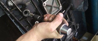
The figure below shows the geometric diagram of the clamping mechanism. The fixed part is pressed against the supporting surface as a result of turning the eccentric handle counterclockwise around an axis rigidly fixed relative to the support.
Program in MS Excel:
In the example shown in the screenshot, based on the given dimensions of the eccentric and the force applied to the handle, the mounting size from the axis of rotation of the cam to the supporting surface is determined, taking into account the thickness of the part, the self-braking condition is checked, the clamping force and the force transfer coefficient are calculated.
The value of the friction coefficient “part - eccentric” corresponds to the case “steel on steel without lubrication”. The value of the friction coefficient “axle - eccentric” is selected for the “steel on steel with lubrication” option. Reducing friction in both places increases the power efficiency of the mechanism, but reducing friction in the area of contact between the part and the cam leads to the disappearance of self-braking.
Algorithm:
9. φ 1 =arctg ( f1 )
10. φ 2 =arctg ( f2 )
11. α =arctg (2* e / D)
12. R = D/ (2*cos ( α ))
13. A = s + R *cos ( α )
14. e ≤ R * f1 + ( d /2) * f2
If the condition is met, self-braking is ensured.
15. F = P * L * cos ( α )/( R * tan ( α + φ1 )+( d /2)* tan ( φ2 ))
16 . _ k = F/P
If, based on a given clamping force or force transfer coefficient, it is necessary to determine the dimensions of the eccentric, then this inverse problem can be easily solved using the Excel “Parameter Selection” service. What it is and how to use this service is described in detail and shown in the video at the end of the article about the heat exchanger.
Servicing brake discs and pads
Wear and replacement of discs
Brake disc wear is directly related to the driver's driving style. The degree of wear is determined not only by mileage, but also by driving on bad roads. Also, the degree of wear of brake discs is affected by their quality.
The minimum allowable thickness of a brake disc depends on the make and model of the vehicle.
The main factors indicating that the front or rear brake discs need to be replaced are:
- disc beating when braking;
- mechanical damage;
- increase in braking distance;
- decrease in the level of working fluid.
Wear and replacement of pads
Brake pad wear primarily depends on the quality of the friction material. Driving style also plays an important role. The more intense the braking, the greater the wear.
The front pads wear out faster than the rear ones due to the fact that they experience the main load during braking. When replacing pads, it is better to change them at the same time on both wheels, be it rear or front.
Pads installed on one axle can also wear unevenly. This depends on the health of the working cylinders. If the latter are faulty, then they compress the pads unevenly. A difference in the thickness of the linings of 1.5-2 mm may indicate uneven wear of the pads.
There are several ways to determine whether your brake pads need to be replaced:
- Visual, based on checking the thickness of the friction lining. Wear is indicated by a lining thickness of 2-3 mm.
- Mechanical, in which the pads are equipped with special metal plates. As the linings wear out, the latter begin to come into contact with the brake discs, which causes disc brakes to squeak. The reason for squeaking brakes is abrasion of the lining up to 2-2.5 mm.
- Electronic, which uses pads with a wear sensor. As soon as the friction lining wears down to the sensor, its core comes into contact with the brake disc, the electrical circuit is closed and the indicator on the dashboard lights up.
Eccentric clamp
The eccentric clamp is an improved design clamping element. Eccentric clamps (ECC) are used for direct clamping of workpieces and in complex clamping systems.
The above considerations force, where possible, to replace manual screw clamps with quick-release clamps.
Although the eccentric clamp is fast, it does not provide high clamping force on the part, so it is used only for relatively small cutting forces.
Advantages:
Flaws:
Eccentric Clamp Design
Round eccentric 1, which is a disk with a hole offset relative to its center, is shown in Fig. 113, a. The eccentric is freely mounted on axis 2 and can rotate around it. The distance e between the center C of disk 1 and the center O of the axis is called eccentricity.
A handle 3 is attached to the eccentric, by turning which the part is clamped at point A (Fig. 113, b). From this figure it can be seen that the eccentric works like a curved wedge (see shaded area). To prevent the eccentrics from moving away after clamping, they must be self-braking. The self-braking property of eccentrics is ensured by the correct choice of the ratio of the diameter D of the eccentric to its eccentricity e. The ratio D/e is called the eccentric characteristic.
Thus, all eccentric clamps, whose diameter D is 14 times greater than the eccentricity e, have the property of self-braking, i.e., they provide reliable clamping.
Eccentric clamping mechanisms include eccentric cams, supports for them, trunnions, handles and other elements. There are three types of eccentric cams: round with a cylindrical working surface; curved, the working surfaces of which are outlined along an Archimedes spiral (less often - along an involute or logarithmic spiral); end
Round eccentrics
Due to ease of manufacture, round eccentrics are most widespread.
A round eccentric (in accordance with Figure 5.5a) is a disk or roller rotated around an axis displaced relative to the geometric axis of the eccentric by an amount A, called eccentricity.
Curvilinear eccentric cams (in accordance with Figure 5.5b) compared to round ones provide stable clamping force and a larger (up to 150°) rotation angle.
Cam materials
Eccentric cams are made of steel 20X, carburized to a depth of 0.8...1.2 mm and hardened to a hardness of HRCe 55-61.
Types of eccentric clamps
Eccentric cams are distinguished by the following designs: round eccentric (GOST 9061-68), eccentric (GOST 12189-66), double eccentric (GOST 12190-66), eccentric forked (GOST 12191-66), eccentric double-bearing (GOST 12468-67) .
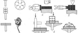
The practical use of eccentric mechanisms in various clamping devices is shown in Figure 5.7
Calculation of eccentric clamps
The initial data for determining the geometric parameters of the eccentrics are: tolerance δ of the size of the workpiece from its mounting base to the place where the clamping force is applied; angle a of rotation of the eccentric from the zero (initial) position; required force FZ of clamping the part. The main design parameters of eccentrics are: eccentricity A; diameter dc and width b of the eccentric pin (axis); eccentric outer diameter D; width of the working part of the eccentric B.
Calculations of eccentric clamping mechanisms are performed in the following sequence:
Calculation of clamps with a standard eccentric round cam (GOST 9061-68)
1. Determine the stroke hk of the eccentric cam, mm:
If the rotation angle of the eccentric cam is not limited (a ≤ 130°), then
Dismantling
Replacing an eccentric in a bathroom begins with dismantling outdated or unusable equipment. Carrying out the work in this sequence will allow you to correctly select a new device, taking into account all the features of pipe supply and the wishes of the customer.
How to unscrew the eccentric? It is recommended to perform the work in the following sequence:
- shutting off the water supply. If you do not first shut off the flow of water to the mixer, then replacing the eccentrics will lead to flooding of the bathroom and neighbors living on the lower floors;
- disconnecting the shower hose from the mixer;
- dismantling the mixer. To perform this work, it is necessary to loosen the nuts securing the device using an adjustable wrench or wrench of the appropriate size;
Removing the faucet in the bathroom
- removing the reflector - a special decorative device that covers the junction of the pipes and the mixer. The reflector is installed by screwing onto the eccentric. Therefore, to dismantle it, it is enough to unscrew the device;
- dismantling (unscrewing with a wrench) eccentrics.
Unscrewing the device from the pipe
Unscrewing the eccentrics from the pipes must be done extremely carefully so as not to damage the threads on the pipes.
After completing work on removing the eccentrics, it is necessary to clean the walls, pipes and other components from accumulations of dirt, rust and other types of contaminants.
Introduction
The machine consists of three main structural elements:
The base and the sawing table itself are not very complex structural elements. Their design is obvious and not so complicated. Therefore, in this article we will consider the most complex element - the parallel stop.
So, the rip fence is a moving part of the machine, which is a guide for the workpiece and it is along it that the workpiece moves. Accordingly, the quality of the cut depends on the parallel stop because if the stop is not parallel, then either the workpiece or the saw blade may become jammed.
In addition, the parallel stop of a circular saw must be of a rather rigid structure, since the master makes efforts to press the workpiece against the stop, and if the stop is displaced, this will lead to non-parallelism with the consequences indicated above.
There are various designs of parallel stops depending on the methods of attaching it to the circular table. Here is a table with the characteristics of these options.
| Rip fence design | Advantages and disadvantages |
| Two-point mounting (front and rear) | Advantages: · Quite rigid design, · Allows you to place the stop anywhere on the circular table (to the left or right of the saw blade); · Does not require the massiveness of the guide itself. Disadvantage: · For fastening, the master needs to clamp one end in front of the machine, and also go around the machine and secure the opposite end of the stop. This is very inconvenient when selecting the required position of the stop and with frequent readjustment it is a significant drawback. |
| Single point mounting (front) | Advantages: · Less rigid design than when attaching the stop at two points, · Allows you to place the stop anywhere on the circular table (to the left or right of the saw blade); · To change the position of the stop, it is enough to fix it on one side of the machine, where the master is located during the sawing process. Disadvantage: · The design of the stop must be massive in order to ensure the necessary rigidity of the structure. |
| Fastening in the groove of a circular table | Advantages: · Quick changeover. Disadvantages: · Complexity of design, · Weakening of the circular table structure, · Fixed position from the line of the saw blade, · Quite a complex design for self-production, especially from wood (made only from metal). |
In this article we will examine the option of creating a parallel stop design for a circular saw with one attachment point.
What is a bicycle quick release?
The eccentric type of fastening appeared relatively recently, but has firmly taken its place. It found its main application in fastening bicycle wheels, seat posts and in the construction of folding bicycle racks.
In addition to their main duties, eccentrics are used in fastening various additional bicycle accessories, where clamps are present.
The operating principle of this clamping mechanism is that the cylindrical shaft used with an offset axis converts its rotational motion into translational motion. In other words, when the shaft rotates, the pressure necessary for fixation is created at the point of fastening contact.
Advantages and disadvantages of eccentrics
The main reason for the appearance of this fastener is its convenience and ease of use. In order to dismantle or secure this or that equipment, you do not need wrenches, and it will take a few seconds. In terms of reliability and tightening force, the eccentric is not inferior to traditional nut fasteners.
Advantages of eccentrics:
- It is difficult to underestimate them on the road, when there is a need to quickly dismantle the wheel to repair it.
- When adjusting the saddle height while simultaneously centering it relative to the bicycle frame, this fastener is indispensable.
- Not everyone likes to carry a set of wrenches with them. It’s not as difficult as it is not aesthetically pleasing: driving with rattling keys in your pouch.
Disadvantages of the eccentric design:
Unlike a regular nut, this design is more complex and therefore more susceptible to depreciation.
With prolonged use, the eccentric springs weaken and the fastening becomes unreliable.
In practice, of course, no one lost the wheels, but the consequences will not be slow to make themselves known. The main one is a violation of brake adjustment, primarily disc brakes.
You can detect a loose fastening by changing the wheel travel - play appears.
Ease of handling the fasteners makes life easier not only for the owner of the bicycle, but also for other unscrupulous citizens.
Arriving at the parking spot of a two-wheeled “horse”, you can only find a fastened frame with a steering wheel. Good wheels and a high-quality saddle with a sub-seat are an excellent trophy for “unclean” colleagues.
Therefore, it will not be possible to save on the weight of wrenches, since their place will be taken by anti-theft locks and blockers.
Eccentric clamps
Eccentric clamps . For large production programs, quick-release clamps are widely used. One type of such manual clamps is eccentric, in which clamping forces are created by turning the eccentrics.
Significant forces with a small contact area of the working surface of the eccentric can cause damage to the surface of the part. Therefore, usually the eccentric acts on the part through the lining, pushers, levers or rods.
Clamping eccentrics can have different working surface profiles: in the form of a circle (round eccentrics) and with a spiral profile (in the form of a logarithmic or Archimedean spiral).
A round eccentric is a cylinder (roller or cam), the axis of which is located eccentrically with respect to the axis of rotation (Fig. 176, a, b). Such eccentrics are the easiest to manufacture. A handle is used to turn the eccentric. Eccentric clamps are often made in the form of crank shafts with one or two supports.
Eccentric clamps are always manual, so the main condition for their correct operation is maintaining the angular position of the eccentric after it is rotated for clamping - “self-braking of the eccentric.” This property of the eccentric is determined by the ratio of the diameter O of the cylindrical working surface to the eccentricity e. This ratio is called the eccentric characteristic. At a certain ratio, the condition for self-braking of the eccentric is satisfied.
Typically, the diameter B of a round eccentric is set for design reasons, and the eccentricity e is calculated based on the self-braking conditions.
The line of symmetry of the eccentric divides it into two parts. You can imagine two wedges, one of which secures the part when turning the eccentric. The position of the eccentric when it comes into contact with the surface of a minimum size part.
Original designs
- An anchor in mountaineering in the form of a triangular plate with a cable, used in belay devices for automatically clamping the rope in the event of a fall.
- Friend (mountaineering) - a bookmark in mountaineering, consists of two eccentrics on the same axis, directed towards each other. When this backfill is inserted into a crack and force is applied to the central axis, the eccentrics rest with their outer sides against the surface of the crack, and with their centers against each other, and are reliably jammed. To remove the bookmark, you need to remove the load and bring the eccentrics towards each other.
- In the bass drum pedal mechanism, thanks to the eccentric, you can adjust the degree of rigidity, beater speed and impact force. For the first time, eccentrics were offered in 1961 by the company, later sold to DW and Tama. Thanks to the development of the Pearl company, it became possible to change the eccentrics, which allows you to adapt the pedal to any playing technique.
- Eccentric-cycloidal gearing - one of the wheels has an eccentric profile.
- An eccentric is a quick-tightening mechanism for securing a bicycle wheel axle. With its help you can remove/install the wheel without tools.
Preparing for work
Before you begin, you need to decide on the necessary set of tools and materials that will be needed during the work process.
The following tools will be used for work:
During the work you will also need the following materials:
Let's look at eccentric clamps. An eccentric is a connection in one part of two elements - a round disk of radius r (Figure 2.39 - Eccentric) and a flat single-bevel wedge. When the eccentric rotates around the axis of rotation of the disk 0, the wedge enters the gap between the disk and the workpiece and develops a clamping force Q.
Figure 2.39 – Eccentric
The working surface of the eccentrics can be a circle (circular) or a spiral (curvilinear). Their difference lies in the fact that in the development of circular eccentrics the flat wedge turns out to be curvilinear with a variable angle α depending on the angle of rotation β (Figure 2.39, b - Eccentric), and for curved eccentrics α does not depend on β. This means that curved eccentrics create a stable clamping force in a batch of workpieces, while circular eccentrics do not. When clamping with circular eccentrics, depending on the fluctuation in the size of the NTn in a batch of workpieces, the working angle of rotation β changes, and, consequently, the angle α and the clamping force Q. At the same time, the manufacturing technology of circular eccentrics is much simpler than curved ones. Therefore, circular eccentrics with an angle β=30÷135° are widely used to reduce vibrations of Q1 in a batch.
Figure 2.40 — Diagram of a clamping mechanism with an end cam
Cam clamps are the fastest acting of all manual clamping mechanisms. In terms of speed, they are comparable to pneumatic clamps.
The disadvantages of eccentric clamps are: small amount of working stroke, limited by the amount of working stroke, limited by the amount of eccentricity; increased fatigue of the worker, since when unfastening the workpiece the worker must apply force due to the self-braking property of the eccentric; unreliability of the clamp when the tool operates with shocks or vibrations due to the danger of self-detachment.
Despite these disadvantages, eccentric clamps are widely used in fixtures, especially for small-scale and mass production.
When designing an eccentric clamp, it is necessary to determine its design and dimensional parameters based on the clamping force Q required to secure the workpiece. The initial data for the calculation are: Tn – tolerance for the size H of the workpiece from the base to the point of application of the clamping force; β – working angle of rotation of the eccentric from the zero (initial) position; Q is the force required to secure the workpiece. The result of the calculation should be: e - eccentricity of the eccentric, d - diameter of the trunnion, R - radius of the working surface of the eccentric, B - width of the working surface, l - length of the handle (with manual clamping).
At angle β
Typical designs and uses
An eccentric consists of two rigidly connected shafts with offset axes (or a shaft with an off-center hole). One of the shafts (or axle) is inserted into the ring on the support, a ring
, perceiving the resulting movement.
At its core, this is
very small crank However, most often this design is used for adjustments: supplying drum brake shoe supports, adjusting the tension of drive belts on engines, matching water mixer inputs and wall outlets, etc.
The eccentric itself is designed as in the previous paragraph, however, the resulting movement is perceived at one or two opposite points by the plane (end) of the translational or swinging link - the pusher
.
At its core, this is the (simplest) version of a cam mechanism
, creating a harmonious movement in which the movement of the pusher is proportional to the cosine (or sine) of the angle of rotation of the eccentric. Most often used to drive pistons or membranes of low-power pumps (engine fuel pumps), as well as for small translational movements, for example, converting the rotational movement of a lock handle into the reciprocating movement of a bolt-latch.
An eccentric is a disk or disk sector with an off-center hole with a small eccentricity (the distance between the axes of the disk and the hole). Used to create a compressive force between the center of rotation of the eccentric (usually connected by a rod to the opposite side of the object being compressed) and the point of contact of the object with the outside of the eccentric. Uses wedge
, which, in fact, is the crescent-shaped section of the eccentric between the rotation hole and the outer surface. The eccentric is rotated using a directly attached handle. This principle is used for an easily clamped bolt used in bicycles to quickly fix the position of its parts, as well as for clamping workpieces in machine tools and pullers (pin wrenches).
Eccentric coupler: types, application features and mounting options
The requirements for furniture fasteners are as follows: 1. The fasteners must provide the necessary strength and, no less important, the accuracy of the connection. 2. Be inconspicuous or at least aesthetically attractive. 3. Additive (drilling holes for installing fasteners) should be simple and take as little time as possible. The fewer holes, the better. 4. Furniture assembly should be simple and convenient. 5. The connection should be cheap (you need to consider not only the cost of the fittings, but also the man-hours and machine-hours spent on both the additive and the assembly of the furniture). Often, the use of more expensive fittings can significantly reduce the cost of furniture as a whole + increase its consumer properties (quality) Notes on the topic: Unfortunately, neither “confirmat” nor eccentric ties such as “Minifix” or “Rafix” are self-sufficient, since they do not provide centering of furniture blanks and require the installation of centering dowels nearby. It seems to me that the manufacturers of these eccentric couplers deliberately make them this way, without relying on the accuracy of the additive. Therefore, if we count the holes required for the additive, then 4 holes require (two each in the face and end) require confirmations, 4 holes require Rafix type ties (3 in the face and 1 in the end) and 5 holes require “Minifixes” (3 in end and 2 in face). This is bad. In addition, you can count how many parts a connection consists of using a “minifix”: dowel, liner, rod, eccentric, plug. Even if you do without the futurka, you still get three elements. Therefore, all of the above options for fittings should be considered as something not exactly cheap, but labor-intensive and complex for “garage workers.” Is there anything without the listed disadvantages? The answer is yes. Eat. Some are presented in Russia. Such accessories are not produced in Russia, but are imported. There are different options. They require drilling not 4 or 5 holes, but only 2 (only in the face or in the face and in the end) or 3 (2 in the face, one in the end), and consist of only 1 or 2 elements (maximum). The time for assembling furniture is reduced by 2-5 times. Production time is reduced in proportion to the reduction in quantity, as well as movement from one production site to another. There are options for fittings that have never been imported to Russia. Including, for example, completely hidden ones. The disadvantages of such fittings are the following: it requires a more precise additive and is more expensive. And further. Few people know about such accessories. I have no connection with companies that supply such accessories and therefore there is no reason to advertise sellers and manufacturers of such accessories. Reply
What it is
This is the most common type of furniture fastener, which consists of the eccentric itself, a stand and a foot. The latter acts as a nut. All of them are divided into the following types:
- diameter and size;
- the length of the stand itself;
- type of rack fastening (screw or self-tapping screw);
- type of foot.
Similar fasteners are used for products made of chipboard or laminated chipboard.
according to the “assembly-disassembly” type. If you are making furniture for yourself and know that it will often move from place to place, then it is better to use just such elements.
These connections are preferably used during assembly where no traces of fasteners should be visible. Only the eccentric itself will be visible, and then only from the inside. In the future, it can be hidden with an additional plug.
Making a circular saw
Preparation of blanks
A couple of points to note:
We drill a 22 mm hole in the end for the handle.
It is better to do this by drilling, but you can simply hammer it with a nail.
The circular saw used for work uses a homemade movable carriage made of (or, as an option, you can whip up a false table), which is not too bad to be deformed or damaged. We hammer a nail into this carriage in the marked place and bite off the head.
As a result, we get a smooth cylindrical workpiece that needs to be processed with a belt or eccentric sander.
We make a handle - it is a cylinder with a diameter of 22 mm and a length of 120-200 mm. Then we glue it into the eccentric.
Transverse part of the guide
Let's start making the transverse part of the guide. It consists, as mentioned above, of the following details:
Upper transverse clamping bar
Both clamping bars - upper and lower - have one end that is not straight 90º, but inclined (“oblique”) with an angle of 26.5º (to be precise, 63.5º). We have already observed these angles when cutting the workpieces.
The upper transverse clamping bar serves to move along the base and further fix the guide by pressing against the lower transverse clamping bar. It is assembled from two blanks.
Both clamping bars are ready. It is necessary to check the smoothness of the ride and remove all defects that interfere with smooth sliding; in addition, you need to check the tightness of the inclined edges; There should be no gaps or cracks.
With a tight fit, the strength of the connection (fixation of the guide) will be maximum.
Assembling the entire transverse part
Longitudinal part of the guide
The entire longitudinal part consists of:
This element is made from the fact that the surface is laminated and smoother - this reduces friction (improves sliding), and is also denser and stronger - more durable.
At the stage of forming the blanks, we have already sawed them to size, all that remains is to refine the edges. This is done using edge tape.
The edging technology is simple (you can even glue it with an iron!) and understandable.
The base of the longitudinal part
We also additionally fix it with self-tapping screws. Do not forget to maintain a 90º angle between the longitudinal and vertical elements.
Assembly of transverse and longitudinal parts.
It is important to maintain an angle of 90º, since the parallelism of the guide with the plane of the saw blade will depend on it.
Installation of the eccentric
Installing the guide
It's time to attach our entire structure to the circular saw. To do this, you need to attach the cross stop bar to the circular table. Fastening, as elsewhere, is carried out using glue and self-tapping screws.
... and we consider the work finished - the circular saw is ready with your own hands.
Advantages and disadvantages
The furniture connection has its undeniable advantages, which are appreciated by craftsmen. Namely:
- Rapidity. With its help, you can assemble the product without any extra effort. To work, you just need to prepare a regular flat-head screwdriver.
- This is the most reliable type of connection. Withstands heavy loads. Ideal for frequent assembly and disassembly. At the same time, the quality and strength of the connection is not lost.
- Does not spoil the front side of the product at all. Aesthetics are important when assembling. They will be noticeable only from the inside of the products.
It has good positive qualities, but there are also some disadvantages. Let's look at them:
- High price. In contrast, ordinary confirmations are considered budget elements. If a large number of connections are expected, then the presence of eccentrics will increase its price several times.
- Complex installation technology. Using confirmation is much easier. It only needs two holes. With minifix everything is much more complicated. You will need three of them.
- It is necessary to have precise equipment. Without it, it is difficult to make precise markings perfectly straight. Otherwise, it will not be possible to assemble the furniture.
Such fasteners do not have any serious disadvantages. If you want your products to be strong and durable, then you should choose only such an element.
Video: installing a furniture eccentric coupler
Easy to manufacture, with a high gain, a fairly compact eccentric clamp, which is a type of cam mechanisms, has another, undoubtedly, main advantage...
... – instantaneous performance. If in order to “turn on and off” a screw clamp it is often necessary to make at least a couple of turns in one direction and then in the other, then when using an eccentric clamp it is enough to turn the handle only a quarter turn. Of course, they are superior to eccentric ones in terms of clamping force and working stroke, but with a constant thickness of the fastened parts in mass production, the use of eccentrics is extremely convenient and effective. The widespread use of eccentric clamps, for example, in stocks for assembling and welding small-sized metal structures and elements of non-standard equipment, significantly increases labor productivity.
The working surface of the cam is most often made in the form of a cylinder with a circle or Archimedes spiral at the base. Later in the article we will talk about the more common and more technologically advanced round eccentric clamp.
The dimensions of eccentric round cams for machine tools are standardized in GOST 9061-68*. The eccentricity of the round cams in this document is set to 1/20 of the outer diameter to ensure self-braking conditions over the entire operating range of rotation angles at a friction coefficient of 0.1 or more.
The figure below shows the geometric diagram of the clamping mechanism. The fixed part is pressed against the supporting surface as a result of turning the eccentric handle counterclockwise around an axis rigidly fixed relative to the support.
The position of the mechanism shown is characterized by the maximum possible angle α
, while the straight line passing through the axis of rotation and the center of the eccentric circle is perpendicular to the straight line drawn through the point of contact of the part with the cam and the center point of the outer circle.
If you turn the cam 90˚ clockwise relative to the position shown in the diagram, then a gap is formed between the part and the working surface of the eccentric equal in magnitude to the eccentricity e
. This clearance is necessary for free installation and removal of the part.
Program in MS Excel:
In the example shown in the screenshot, based on the given dimensions of the eccentric and the force applied to the handle, the mounting size from the axis of rotation of the cam to the supporting surface is determined, taking into account the thickness of the part, the self-braking condition is checked, the clamping force and the force transfer coefficient are calculated.
The value of the friction coefficient “part - eccentric” corresponds to the case “steel on steel without lubrication”. The value of the friction coefficient “axle - eccentric” is selected for the “steel on steel with lubrication” option. Reducing friction in both places increases the power efficiency of the mechanism, but reducing friction in the area of contact between the part and the cam leads to the disappearance of self-braking.
Source
Structural design
The classic ratchet mechanism is designed to transmit intermittent rotation in one direction. Most often installed for gears. The ratchet mechanism in question is characterized by the following features:
When manufacturing the workpiece, casting and forging technology is used
This ensures a high degree of reliability. The most important part of any device can be called gears. They are represented by wheels made of metal, on the surface of which there are teeth. The number of teeth on the surface depends on the intended purpose of the mechanism
As practice shows, the most common version is with 12 teeth for 30-degree rotation. For tensioning belts, a design option is often installed that has only 6 teeth.
Another important design element is the dog. It acts as a locking element. The basic properties of the element and its arrangement, certain functions and dimensions largely depend on the specific model and its field of application.
Do-it-yourself vibrating plate: with an electric motor, gasoline, homemade, drawings, how to make it yourself
Compaction of soil, backfill layer or concrete casting during construction work requires the participation of special equipment. In private construction, problems often arise related to deformation or subsidence of the foundation.
The cause of these events is poor compaction of the sand backfill layer. According to the technology, the density should correspond to the condition of a long-used country road. Checking the quality of the compaction is usually done by walking along the compacted area - if there are no traces of shoes left, the job has been done to the proper standard.
Soil compaction is required not only in critical areas. Conventional tiling of garden paths requires the creation of a layer of sand cushion, which also requires the maximum degree of compaction, otherwise the coating will begin to fail and move apart. It is impossible to achieve high quality work manually, and a vibrating plate comes to the rescue.
For home use, not everyone can purchase a ready-made device, since the cheapest sample will cost 20 thousand rubles. People who are able to operate metalworking tools and a welding inverter prefer to make their own vibrating plates, which saves money and brings the desired result.
Operating principle
The operation of a vibrating plate is based on the use of a rotating shaft with an eccentric, which generates strong vibration. The shaft is mounted on a massive metal base, which with its weight acts on the soil, compacting it due to its weight.
On the same base, a motor is installed, which is necessary to drive the eccentric shaft into rotation. To control the structure and give the installation the desired direction, a long handle is installed.
There are several types of vibrating plates:
- electrical;
- diesel;
- gasoline.
By weight they are divided into:
- light (up to 75 kg);
- universal (from 75 to 90 kg);
- medium-heavy (from 90 to 140 kg);
- heavy (140-200 kg or more).
There are also different ways to move the vibrating plate:
- upright, capable of moving only forward and requiring a platform of sufficient size to turn around;
- reversible, capable of moving both forward and backward, which makes them more convenient in conditions of limited space.
Lightweight and versatile vibrating plates are used for compacting paths, paving slabs, and landscaping work. During construction and foundation work, medium-heavy and heavy-duty installations are required that provide maximum compaction combined with high productivity.
Important! The weight of a vibrating plate created at home should not be too large, otherwise it will be difficult to move it and there will be a danger for the worker servicing the installation.
Mechanism design
Device
The main element of the vibrating plate, from which the creation of the installation begins, is the metal base.
There are steel and cast iron samples, however, the use of cast iron at home is not advisable.
It is capable of cracking, cannot be welded, and is fragile.
Typically, steel sheets with a thickness of 8 mm or more are used. Additional elements are installed on the surface of the base to increase the mass.
They also serve as the basis for installing the engine and vibration mechanism. In most cases, this is a regular shaft mounted on two bearings, on which a load is attached in the longitudinal direction. The rotation of the shaft creates a driving force, which, due to its own weight and inertial force, forms frequent short-term loads on the ground. Drawing
The operating efficiency of a vibrating plate depends on the weight, base area and rotation mode of the eccentric shaft. A slab that is too spacious is not capable of generating high pressure, since the weight of the installation is distributed over the area and reduces the specific pressure.
A small base gives greater efficiency, but it acts too selectively, pointwise. This mode does not allow uniform compaction of the soil over the entire area of the site.
The rotation of the eccentric shaft creates a significant load on all structural elements.
Too intense vibration can destroy the vibrating plate, have a negative impact on the operation of the engine, and negatively affect the well-being of the worker.
An example of a drawing of a gasoline vibrating plate:
Engine selection and installation
The rotation of the shaft is ensured by a motor installed on the base at the rear of the vibrating plate (close to the handle).
Different types are used:
- electric motor;
- diesel;
- petrol.
The choice of vibrating plate motor type is determined by several factors:
- owner capabilities;
- availability of connection to the electrical network;
- specifics of the upcoming use of the installation.
Vibrating plates with a gasoline engine are convenient because they allow you to gain complete independence from network resources (electricity).
They can be used on sites located at a considerable distance from the nearest housing or buildings, in the field, etc.
The only inconvenience is the need to carry a supply of fuel, which may be needed a lot during long-term operation and high engine power. This is excess weight and expense.
A homemade electric vibrating plate is limited in mobility by the length of the connecting cable. At the same time, it only needs to be connected and no longer requires any additional actions.
The main disadvantage of the electric motor is its constant rotation speed, which creates a strong starting torque and overloads the network.
The solution to the problem is to assemble a soft start regulator, which avoids mechanical and electrical overloads.
Attention! Electric motors do not require special care or maintenance, whereas gasoline or diesel units require constant attention.
The motor is mounted on the base of the vibrating plate using rubber cushions that reduce vibration and protect the motor from mechanical destruction.
Plate and frame
The plate is a sheet of metal, the thickness of which can provide sufficient rigidity.
Typically, steel sheets of 8 mm and thicker are used.
The average size of the working surface of the stove is 60*40 cm, although there are other options.
The front and rear edges of the slab are raised for unhindered movement along the surface of the site.
The frame consists of a stand for the engine and eccentric shaft. It also serves as an additional load, which gives the vibrating plate greater efficiency and increases the amount of forcing force. Another task that the frame solves along the way is strengthening the rigidity and strength of the base, compensating for mechanical loads from the rotating rotor.
The design of the homemade frame can be anything. The main task is to strengthen and weigh the slab, so they use pieces of channel bars, rails and other massive and durable elements. The only thing to remember is that the vibrating plate must sooner or later be placed in storage, which may require carrying it manually. Excessive weight will create difficulties.
Vibration mechanism
The vibration mechanism of a vibrating plate, or vibration exciter, can have two design options:
- unbalanced, which is a rotor unbalanced relative to the axis of rotation;
- planetary, using the energy of moving elements that move along special closed paths.
Making a planetary mechanism at home is impractical, since it is difficult both to create and to maintain. It is difficult to make an unbalanced vibrator, and the magnitude of the driving force is the same in both cases, so the choice is obvious.
The eccentric rotor is mechanically connected to the engine via a drive belt. To do this, pulleys located in the same vertical plane are installed on both elements. With their help, you can adjust the gear ratio and change the vibration frequency of the installation.
Additional items
Additional elements are:
- handle (carrier) used to guide the vibrating plate during operation;
- a trolley on which the device is installed when moving from one place to another;
- tension mechanism, which ensures tight contact of the drive belt with the pulleys of the engine and vibration mechanism.
The handle is a long U-shaped bracket made of a tube. It is attached to the plate through a swivel joint, which partially compensates for vibration and protects the worker from its effects.
The trolley is a separate element, although rigid mounting options are available. It is brought under the stove, the unit tilted towards itself by the handle, supported on a trolley and transported to the desired location. When rigidly mounted, the legs with wheels are installed on the base in an inverted position. If it is necessary to move the vibrating plate, the installation is turned over and transported to another location.
The tensioning mechanism ensures tight contact between the drive belt and pulleys. It is important that the roller has a groove that matches the groove of the pulleys. This will help extend the life of the belt.
If the vibrating plate roller is installed on the outside, the groove size must match the back of the belt.
For tensioning, an adjusting screw is used, which allows you to loosen the belt for replacement or tighten it to working condition.
How to do it yourself: step-by-step assembly
Let's look at the process of how to make a homemade vibrating plate for soil compaction. Procedure:
- Using a grinder, a slab (base) is cut out. The size is chosen based on your own ideas, it is recommended to stick to the average value of 60*40 cm.
- Along the edges, cuts are made at a distance of 7 cm (front) and 5 cm (back), to a depth of about 5 mm. Along the line of cuts, the edges are bent upward by 25° so that the slab does not cling to the ground and does not get stuck.
- Two pieces of channel are welded onto the top of the slab, reinforcing the base and edges. It is necessary to ensure that they are in the same plane.
- On the back side, holes for mounting the engine are drilled or burned with a welding electrode in the channels. If necessary, a metal platform with mounting holes is pre-welded.
- The engine is installed using rubber cushions.
- Eyelets are installed for attaching the handle.
- The rotor with the eccentric is manufactured separately and installed on the plate in finished (assembled) form. It is a shaft installed in the hub. One of them is blind, the second is through. A section of shaft passes through it, onto which the pulley is installed. It is necessary to ensure the alignment of the pulleys, otherwise the drive belts will have to be changed every shift.
- The tensioning device is attached to the frame in a convenient place for use. It is usually installed in the middle, between the pulleys, at the point of maximum belt sag. It is important to ensure that all pulleys and the tension roller are placed in the same plane.
- It is recommended to cover the rotating rotor with a protective cover to prevent injury.
- The handle is installed, a test run of the vibrating plate is made, and the functionality is checked. Detected problems or flaws are eliminated and necessary amendments are made.
Putting the vibrating plate into operation is possible only after all defects have been completely eliminated. It’s rare that anyone manages to get the expected result the first time, but after corrections, the installation usually starts working in the desired mode. The main setting is to determine the optimal eccentric size and select the speed mode of operation.
A homemade vibrating plate, no matter how it turns out, will provide a much better result than trying to compact the backfill layer manually. All detected deficiencies will be eliminated, and additions or improvements to the design will appear as operation progresses. The final result can compete with industrial designs, if not outstrip them in terms of efficiency and quality of work.
The main advantage of homemade devices is the ability to correct or change the design at any time, or add additional elements.
Such actions are impossible with ready-made vibrating plates, since the design of such technical means rarely allows for changes.
The quality and speed of labor-intensive operations with bulk materials is worth the effort and time spent on creating homemade plants.
Quick-release clamp - homemade
In the arsenal of carpenters who perform a large amount of gluing work, there are cabinet clamps such as Bessey KR Revo, GROZ clamps, quick-release or pipe clamps.
It’s difficult to imagine a replacement for a professional carpenter’s clamp, but what to do when you don’t have a clamp at hand, have nowhere to buy it, or can’t order delivery.
A solution to this problem is offered by a Japanese woodworking master and part-time blogger from the YouTube channel Self-Build
. He showed his vision of how to create craft DIY clamps in a new video.
The idea is to use the most ordinary materials for manufacturing: scraps of wooden beams of various sizes and simple fasteners - such as perforated plates and bolts with nuts. The clamping mechanism of the clamp will securely fix the parts, and at the same time, it can be easily adjusted to different lengths of the workpieces.