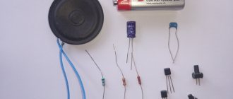
Cables are a type of wire that is used to connect various printed circuit boards and electronic elements inside a device. They have many varieties and soldering features. Depending on the internal cross-section of the installed contacts, the conductivity will be higher or lower. This also applies to the type of soldering material.
If the question arises of how to restore a cable if it is damaged yourself, then many different nuances should be taken into account. The article will describe the main elements and provide information on how to solder contacts on various devices.
Peculiarities
Before you start considering the question of how to restore a torn cable, you should study its features. Depending on the type of device or printed circuit board, this type of wire can be either flat or circular. In addition, various elements in the form of technical varnish, graphite coating or rubberized braiding can be applied over the contacts and the conductor itself.
If the cable on the moving modules of the device is damaged, for example, on the print head of the printer, then it is necessary to clean the contacts from the rubberized braid. Loops on screens and phones can be applied on top of a printed silicon board. They have a flat appearance and are protected by graphite coating.
A little about the train
The cables are insulated wires. They can be either single or combined into one group. In phones and tablets they are usually ribbon. They look like plastic tape, but there are copper strands of wires running inside it. Often this type of cable is subject to various deformations - it can be torn, cut, dissolved by various liquids, or it can simply move away from the board. It can either be replaced entirely or a spot repair can be made. It is the breaking of the cable wires that is a common reason why a tablet or phone does not turn on. Therefore, if you decide to figure out this problem yourself rather than take the device for repairs, then first you need to disassemble the device and check the condition of the cable. Typically, a device called an ohmmeter is used to find a faulty wire. To use it, first the connecting elements are extended to the sides, then they look for a faulty contact that “flickers.”
Purpose
The main purpose of each loop is to transmit a short or long electrical pulse between the device modules. Depending on the type and thickness, as well as the material of the conductor, the signal is transmitted at a certain speed.
This is important to consider, since if it is necessary to replace the conductive element itself, a copper wire of the required alloy will be required. Otherwise, contact may not proceed. The cables are convenient to place in compact equipment models due to their small size. Often this type of connection is used in mobile phones, laptops or screens.
Conductors can vary in the number of wires and contacts inside. Stubs with a single conductor element are usually installed on top of silicon circuit boards. If you need to connect a screen or hard drive, then a multi-threaded connection type will be used. It can have up to 40 grip points. It is these cables that are most often subject to damage, since soldering occurs on all contacts. If at least one of them is damaged, the device will cease to function normally.
CONNECTION DIAGRAMS FOR SECURITY DETECTORS
The connection diagram for the detector ( Astra, Harp, Steklo, Rustle, Photon
, in short, any) is always given in the passport of a specific alarm device, but only contains the assignment of the terminal block contacts.
It is worth noting that the example given here is maximum and is rare.
Almost always the block has one pair of monitoring station contacts and power connection contacts. Two pairs of monitoring station contacts are sometimes found on some combination detectors.
The additional contact “RES” is inherent in the “Astra 5” detectors, the TMP contacts are typical for the “Shoroh” detectors. The abbreviations used indicate:
- 12V GEN “+” - polarity and supply voltage
- Monitoring station - control panel pair (detector output informing about its status)
- REZ - additional contact for connecting the terminal element of the alarm loop (resistor). It is not connected in any way with the detector circuit, it just hangs in the air, that is, it is a technological
- TMP (TAMP) - tamper switch contacts - open when the detector housing is opened
A diagram for connecting several detectors to an alarm loop (that is, connecting them to each other) is usually not given, and this, despite its apparent simplicity and obviousness for beginners, can pose a serious problem.
Therefore, the connection of a remote control pair of such detectors to the alarm loop is carried out sequentially, with the installation of the final element of the alarm loop, in most cases a resistor (R), after the last detector (IN).
How the alarm sensors actually connect to each other to form an alarm loop is shown in the following four figures.
This scheme for switching on detectors is very rare.
The only thing that can be useful from it is connecting tamper contacts (for example, for “Shorokh 2” detectors). True, often these contacts, even if they exist, are ignored, leaving them hanging in the air.
The following example of connecting security detectors is of practical importance and is used, for example, when organizing an alarm loop for the second line of security using Astra 5 detectors.
I want to say that the color scheme in the wiring diagrams of alarm sensors is used not only for beauty and ease of perception.
In practice, the connection of security detectors is carried out by a four-wire line, each of the wires of which has its own color, which greatly facilitates the installation of the alarm loop.
The third switching circuit is a special variant of the previous one and is used when the detector does not have the “RES” terminal. (The black circle indicates soldering of wires).
The options discussed above are good when using a hidden alarm cable.
In this case, the connecting line is led out of the wall or other building structure directly under the detector, which covers the output location, and all switching is carried out in the alarm device housing (the design of the room does not suffer).
The disadvantages of this method of installing detectors are the difficulty of maintenance (to find a fault, you need to open the device case), the relatively small free space inside the case, and the miniature size of the terminal block. Sometimes this method of installation becomes truly a piece of jewelry.
This is especially evident when installing detectors of the alarm loop of the first line of security.
The inclusion of magnetic contact detectors, which have flexible terminals, along with terminal detectors, makes switching inside the device body, as a rule, impossible.
You can, of course, use soldering, but then the question again arises of the convenience of troubleshooting during operation of the fire alarm system (sometimes errors made during installation).
Malfunctions related to damage
Determining that equipment is damaged due to a loop is quite simple. If you look at the screen of a laptop or TV, then due to damage to the conductor, the matrix will begin to flicker or the image will partially disappear. This is due to the fact that such a connection channel to the main board is responsible for projecting the signal. The damaged area will be broadcast with interruptions in the image precisely at the point where the contacts are soldered.
In any case, you can make sure that the problem is in the cable only by disassembling the device itself and checking the voltage at each of its contacts. Usually such interruptions are visible to the naked eye.
The main visual signs of damage include the following:
- Darkening in the places where the cable conductor goes.
- Kinks and tears in the tape.
- Damaged contacts at solder points.
In any case, such problems cannot be corrected with ordinary glue. Here you will need rosin, tin, alcohol and a soldering station.
CONNECTING AND DISCONNECTING CONNECTORS ON CABLE CABLES
There was a Sony KDL 26P3000 TV in the closet - it’s not a bad television receiver at all and it didn’t work for long, less than three years, but something happened to the image and it began to disappear. Professional specialists at the Sony service center easily agreed to “put it back on its feet” for 12,000 rubles, but considering that it costs 18,000 they politely refused. We bought a new TV, and this one was at my complete disposal. In anticipation of a banal disassembly into its component components, I decided to check the guess made by a radio amateur I knew about a possible malfunction, which there is a chance to correct on my own.
Which devices often need repairs?
Every time the owner of household appliances and electronics is faced with the question of how to restore a cable, he must understand that the operation of soldering or stripping contacts itself carries a certain risk. If you fix a problem on the cable without the necessary tools or materials, there is a risk of damaging neighboring modules.
The owners of the workshops become frequent clients:
- TVs, monitors, laptop screens.
- Keyboards.
- Laptops and PCs.
- Phones.
The problem is not the quality of the conductors themselves, but the risk of damage to them. If we consider a mobile phone, the cable is mainly damaged due to contact with liquid. As a result, the contacts burn out at the soldering points.
Keyboard wires wear out from frequent use of keys and switches. This leads to the fact that the conductor itself wears off over time and conductivity decreases. If we consider laptops and personal computers, the problem may arise due to a power surge or incorrect connection of the conductor itself.
Kolkhozim flexible cable in 15 minutes.
Good day.
Not long ago I saw a heated discussion on the Internet about where to buy foil film. A man needed a flexible cable. Well, it turned out almost like Mendeleev’s - I thought about it while falling asleep. I woke up with an idea. I tried it and it worked.
The base will be thermal tape, also known as Kapton tape (most likely according to the distorted name of the manufacturer), or polyamide tape. This material is new to me, I bought it on DX because it’s cheap, at the behest of the toad. I found details about it here. Surprisingly, I still didn’t know what this cute thing was for :)
Unfortunately, I have only one hand, so I’ll report on the important moments in close-up later, when another victim wanders into my den. - If the need arises. Actually, a video.
Something, as it turned out, is not entirely obvious. Of course, you can apply thermal tape from the side of the microcircuit, but the result will not be a fountain - due to the gap between the wires and the board, it will not stick evenly, the wires will move relative to each other and it will be uneven.
And yet - in theory, you can use any flexible materials - even glue on a rag. Only here is the heat resistance/conductivity... Although I remembered the film for laminators - it might turn out even more interesting.
Source
Screens
The question of how to restore the display cable is quite complex. It all depends on the brand and model of the matrix and the boards to which such a screen is attached. It could be a laptop, monitor, tablet, all-in-one or TV. Each of the listed devices uses its own soldering method and technology for applying binding materials.
Damaged contacts at the coupling points must be completely cleaned. You can use a blade or scalpel for this. Then you will need to strip the wires to fix them in place where they are soldered to the board. It is better to use a soldering iron with a small tip to prevent tin from getting on other elements. If you need to build up a damaged area if it is broken or bent, then you will need a similar wire model. You can find it on the radio market or on the Internet, on thematic resources.
When considering the question of how to restore a cable on a matrix, it is necessary to test each connected element or contact before starting the repair. This is done using a voltmeter. It shows the voltage at each section. This must be done in order to not only find the source of the damage, but also its cause, which may be a damaged part.
How to fix a CD player head cable with your own hands | Geek
I had a Walkman seat (D-NE920) lying around on a shelf at home. A good player, BUT..... It doesn't work. After analysis, it turned out that the reason lies in a broken head cable, so today I will show you how to fix the cable with your own hands.
Disassembly
There's nothing really special inside. The standard components for a CD player are a mechanically driven head and electronics.
Even before disassembly, it was established that half of the cable leading to the head was broken. Unfortunately, I lost the very first photo of what the train originally looked like ((
I was lucky because... the train was one-sided, although there are also double-sided ones. If the conductors pass from both sides, then the possibility of repairing such a loop becomes much more difficult. Although it all depends on manual dexterity and the width of the conductors. I haven't encountered anything like this. Typically, double-sided cables are used in cell phones and laptops to save space.
I received the player itself in a deplorable state and lay quietly on the shelf for a long time. To be honest, I don’t even understand how it was possible to manage to break the train like that.
Here is the player head with a torn cable. All tatters and damaged areas were cut off. Now I will show you how to fix the cable.
How to fix a cable, let's go...
In the photo above you can see that the side of the head is not cut straight, but like a ladder. The ladder goes along the cable conductors.
But there is a ladder on both sides of the cable break.
To restore and fully operate the cable, it is necessary to connect all the broken tracks, and for this it is necessary to solder wires instead of the missing parts of the cable. To reduce the likelihood of shorting the places where the wires are soldered to each other, it is better if they are not on the same line but separated by a ladder.
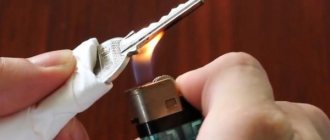
Tinning conductors
In order for everything to go smoothly, it is better to immediately tin the wiring (you can see how to do this in the article on repairing headphones) and also tin the conductors on the cable. To do this, you need to clean off the top insulating layer.
I did this with the edge of a utility knife. It is enough to clean a small area, into which you then need to poke a soldering iron with tin dipped in rosin. The result should be a tin droplet.
Instead of the missing parts of the cable there will be wires from the headphones. They are convenient for three reasons:
- There are always at home .
- Such wires are a mixture of thin copper wires and nylon threads.
Thanks to this, they bend easily , are more durable and thinner. - They are varnished along the entire length.
Accordingly, they do not need any outer insulating braid, which will only thicken them and impede their flexibility.
Soldering the wires
The first step was to restore the outer conductors. Actually, there is no difference where to start, it’s just that the outer contacts turned out to be thicker and the training was done on them)
There were still three thin (~0.1 mm) conductors left in the center. It seemed pointless to me to cut them together with the base of the cable, and in order to separate the soldering points, the excess parts of the conductors were simply torn off.
Now that all the wiring is soldered, you need to make sure there are no errors made during soldering. We take a multimeter in our hands, turn on the resistance measurement mode and check first of all whether we have shorted adjacent conductors to each other. If everything is fine, then now you need to ring each conductor from the beginning of the cable (connector) to the place where something is soldered to the cable:
Protective covering
If something is wrong, we look for it and fix it. When everything is okay, only the final touch remains. To protect against who knows what, I painted the soldering areas with nail polish and covered the problem area with tape.
To be honest, I had a little doubt about the tape; after all, the cable should bend easily when moving the head, but because of the tape, the cable became stiff, but it did bend)
We collect, we try...
This is where the biggest disappointment awaited me... The problem was not only in the cable, but also in the electronics. When the player was connected to charging, it showed charging on the screen, but after lighting up for a couple of seconds it went out, and after that it no longer responded to any buttons. Disconnecting and reconnecting the charger only led to a repetition of the described...
It was 2 o'clock in the morning, the mood to fix it had noticeably diminished and the player went on collecting dust on the shelf... That's such a sad thing