Good day to all! This post will be dedicated to all radio amateurs, or those who are thinking about taking up this simple task. We will talk about such an interesting thing as a “cordless soldering iron”.
It all started when I accidentally saw on the Internet an interesting, previously unseen thing called a cordless soldering iron. And after that I set out to make myself something similar. You can find out what came of this at the end of the article.
For a better understanding, I am attaching a detailed photo report + description.
The design of a soldering iron operating on the pulse principle
A pulse soldering iron is relatively simple. It consists of:
- The tip is the working body, it is a V-shaped piece of copper wire with a thickness of 1 to 3 millimeters, fixed in a holder.
- Power source - supplies low voltage electric current to the tip.
- Pistol grip.
- Device power button.
- Network cable with plug.
- Light bulb or LED to illuminate the work area (optional, but very convenient)
The most complex component is the power source. It converts the mains voltage of 220 V 50 hertz into low voltage high frequency (20-40 kilohertz). The input circuit of the source is connected to the network cable through the power button, and the tip contacts are connected to the output circuit. There are various power supply circuits for pulsed soldering irons.
Pulse soldering iron device
The power source may be built into the handle. The transformer fixed in the housing is heavy and has noticeable dimensions. During prolonged operation, this will greatly tire the operator. In some embodiments, the power source is designed as a separate unit. This increases the safety and ease of use of the device. The device's power button is built into the handle.
The main design differences from a conventional soldering iron:
- Availability of power supply.
- Availability of a power button.
- No heating element.
- There is no need for a stand - the temperature of the soldering iron rises only during soldering, after releasing the button it very quickly cools down to room temperature.
Specific designs of homemade pulse soldering irons may differ from each other depending on what devices formed their basis.
About rewinding an electrical appliance
Beginners often ask the question: how to rewind a soldering iron? Judging by numerous reviews, very often device repair is limited to replacing the burnt nichrome winding. Before starting this procedure, use a special table to calculate the diameter of the wire, as well as the number of turns. For example, how to repair a 200W soldering iron? To do this, select the soldering iron power consumption indicator of 200 W (in the left column of the table). To this value, the winding resistance at a voltage of 220 V will be 242 Ohms. It will be best to rewind the entire reel.
In this case, there will be no weak points in the device. It is very important that the new wire has the same parameters as the old winding. If it is not possible to select a similar insulating layer, then it can be replaced with mica in the form of a tube or plates. You can also use heat-resistant fiberglass or asbestos gaskets to make an insulating layer. After the insulation is ready, wind the winding (first layer) around it. Next, put another layer of insulation on the turns and wind the winding again (second layer). Now all that remains is to connect the ends of the wire to the power cord.
Operating principle
The device is based on the simple physical principle of heating a conductor when passing a strong electric current through it.
When you turn on the device by pressing the button, the input circuit of the power supply is closed, the high voltage is converted by the transformer into low voltage on the secondary winding, and a current arises in the output circuit, which quickly heats the tip. When the button is released, the circuit opens, the current stops flowing and heating stops.
The current strength in the operating circuit reaches 25-50 amperes at a low voltage of about 2 volts. The secondary winding of the transformer must be wound with wire and must have a cross-section several times larger than the cross-section of the tip wire. The same applies to the conductive busbars connecting the ends of the tip to the secondary winding. This will prevent them from overheating and wasting energy to heat them.
Instead of a transformer, switching power supplies have recently begun to be used more and more widely. They make it possible to reduce the weight and dimensions of the unit several times with the same performance.
Current sources for powering pulsed soldering irons
Before you start making your own soldering iron, you should, based on the available materials, decide on the type of source to choose.
Traditionally, a pulse soldering iron used a powerful step-down transformer as a power source and was called that only because of its short-term operating mode.
This device is simple in design, but has a large weight and dimensions.
Power supply
Switching power supplies that became available not so long ago are much more complex. They first rectify the low-frequency mains voltage coming to their input, then convert it into high-frequency (20-40 kilohertz) and then apply it to the primary winding of the transformer. High-frequency transformers are several times smaller in weight and size than low-frequency transformers, so the entire switching power supply, despite its complex design, takes up space several times less than one low-frequency transformer.
To summarize, we can say that transformer sources are simple and reliable, but heavy and bulky.
Pulse ones are much more complex in design, but they save weight and dimensions.
Components of the tool
Before you are interested in how to repair a soldering iron at home, you should know how it works. In this case, if there is a breakdown, it will be easier for you to determine the cause and fix it. The soldering iron device is represented by the following elements:
- Copper rod. It is wrapped in insulating material and housed in a steel tube.
- Heater. This task is performed by nichrome thread.
- Sting. They use solder to directly connect metal parts.
- With a pen. Thanks to it, the master can hold the soldering iron.
- Cord equipped with a plug.
The process of converting a step-down transformer
When choosing a step-down transformer, you should remember that its power should be from 50 to 150 watts. A smaller one will lead to overheating and failure of the device, a larger one will lead to unnecessary weight and bulkiness.
Transformer-based pulse soldering iron
The primary winding does not need to be redone, but the secondary winding should be removed by disassembling the plates. An exact calculation of the secondary winding is not required; it is more important to ensure the maximum cross-section of its wire or bus. Typically, two to six turns are wound. The cross-section should be in the range from 6 to 10 mm2.
Important! The turns of the secondary winding should not touch each other and the transformer core.
If the secondary winding is made of a copper busbar, its ends can be left longer and used as current conductors by attaching the tip directly to them. The absence of unnecessary connections will increase the reliability of operation and improve the temperature regime of the device.
After finishing winding and installation, be sure to check the winding with a tester for absence of short circuit
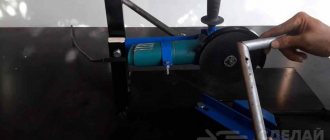
Pulse soldering iron from a step-down transformer
Features of soldering in the groove
Soldering iron repair
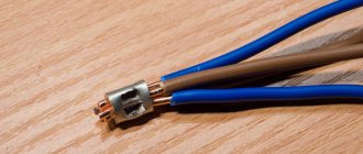
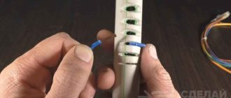
Connecting both single-core and multi-core cables with a cross-section of 3 mm2 without soldering equipment is possible in an original way:
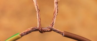
- twist the stripped ends of the wires;
- a piece of foil is bent so as to form an elongated bath;
- a twist is placed in it;
- Flux is applied to the stripped wires and tin powder is added;
- the foil is heated with an open flame from a lighter or other flame source;
- during heating, the twist is rotated around its axis;
- upon completion of soldering, the remaining foil is removed;
- the soldered twist is wrapped in shrink film and heated until a dense layer of insulation is obtained.
Remaking an electronic transformer
The switching power supply for the soldering iron is taken “as is” and undergoes minimal modifications. Most often, a switching power supply is used for halogen lamps with a voltage of 12 volts and a power of 60 watts, but any with similar parameters will do.
Since modern power supplies use non-separable toroidal transformers wound on a ferrite ring and firmly fixed to the board, the old secondary winding is not removed, but simply turned off.
A new secondary winding is made from just one turn of a large-section copper busbar, carefully inserting it into the central hole of the output transformer.
If the wire or busbar found at hand has an insufficient cross-section, then two secondary windings should be made from one turn, connecting them to the current conductors in parallel.
In general, the process of converting an electronic transformer into a pulse soldering iron with your own hands is simpler than in the case of a low-frequency transformer.
Making a soldering iron tip
The tip is the simplest, but nevertheless important component of a soldering iron.
Soldering iron tip
The copper wire should have a diameter of 1-2 millimeters; it should be attached to the busbars using bolted connections with washers. If you have collet connections of this diameter at hand, the soldering iron will take on a much more aesthetic appearance.
After several test solderings, you may have to change the wire diameter. Too thin will overheat itself and overheat the soldered parts; too thick, on the contrary, will warm up slowly, delaying the main work.
By selecting the thickness of the wire, it is necessary to achieve heating of the tip to a stable temperature in 5-7 seconds. An excessive increase in thickness will lead to an increase in power consumption and overheating of the secondary winding of the output transformer. During test soldering, it is necessary to check the degree of its heating, avoiding smoldering or even ignition of the insulation.
Advantages and disadvantages
A do-it-yourself pulse soldering iron will compare favorably with other types of soldering irons in the following ways:
- Low power consumption. It is not spent on heating the workshop, but is spent only at the time of soldering.
- Safety. When not in use, the tip cools down instantly; you cannot get burned with this device, set fire to anything on the workbench, or melt the insulation.
- Ease of use, repair and maintenance. The tip can be made and replaced in a matter of minutes. In addition, the tip can be given any shape for soldering parts in hard-to-reach places or among dense installations.
In addition to the advantages, this type of device also has a disadvantage: its heavy weight and size tire the hand after prolonged use. To avoid this, they use a switching power supply and even place it in a separate unit.
Broken wiring
How to fix a soldering iron with your own hands if the electrical cord is faulty? Judging by numerous reviews, this reason for device failure is considered the most common. You can correct the situation on your own. Many owners simply replace the plug or cord. Of course, it all depends on which part the break occurred in. This defect is correctable, and you can fix it yourself. To determine exactly where the break occurred, you will need to acquire a special device, namely a multimeter. Use the probes of this device to examine the wiring. In the place where the break occurred, you need to reconnect the wires and insulate them.
Making a pulse microcircuit soldering iron
To make a soldering iron, which can be used to solder and solder microcircuits and other electronic components that are particularly sensitive to overheating into printed circuit boards, a specially modified resistor is added to the design of the device, which plays the role of a protective device. An MLT type resistor with a resistance of 8 ohms and a power dissipation of 0.5-2 watts is suitable
DIY soldering iron for microcircuits
In addition, you will need:
- A strip of double-sided foil PCB 10X30 millimeters.
- A piece of steel wire 0.8 mm thick.
- Copper wire for the tip.
- Ballpoint pen body.
- Switching power supply 12-15 volts 1 ampere.
The manufacturing sequence is as follows:
- Remove the paint coating from the resistor by heating it in a muffle furnace or gas burner.
- Use a file or jigsaw to saw off one of the terminals.
- drill a hole with a diameter of 1.1 mm in this place, reaching the internal cavity. The second pin should be connected to the power source; it will also attach the device to the handle.
- Expand the hole in the resistance housing by a cone so as to prevent contact between the tip and the internal walls of the resistor; the second wire to the power supply will need to be soldered to this place.
- The steel wire must be bent in half, a ring with the diameter of the resistor should be bent at the bend (it should fit very tightly) and bent at a right angle.
- Tin the ring, put it on the resistor and solder it so that the ends of the steel wire are directed in the same direction as the remaining lead.
- Cut the board out of a strip of PCB so that on the wide part on different sides there are two contact pads for soldering the ends of the wire and the second terminal of the resistor, respectively, the middle one should fit tightly into the handle body, and the narrow part should have contact pads for soldering wires from the power supply.
- Solder the ends of the wire and the resistance pin to the board, and solder the wires from the power supply on the arc side
- Insert a piece of heat-resistant insulator (the same ceramic, for example) tightly into the resistor hole to prevent contact of the tip with the second terminal.
- Insert the copper tip into the hole. The tip can be given any shape convenient for soldering, bent, flattened, sharpened, etc.
- Pass the wires through the handle body, insert the board into it and connect the wires to the power supply.
Soldering iron device for microcircuits
Working with such a home-made pulse microcircuit soldering iron is safe for microcircuits and does not tire your hand.
Recommendations
When deciding to solder a section of wire using the direct heat method - without tools - it is important to consider the type of components used. For work, standard tin-lead wire and rosin, special foil or paste can be used. The last 2 options are very convenient when heating with a lighter, candle flame, or burner. At the same time, you don’t have to add rosin as a flux - it’s already in the composition.
If you use an improvised tip that imitates the tip of a soldering iron, you need to heat it 2-5 mm from the end. This way the desired temperature will be reached faster. You will have to hold such a tool manually. It is worth stocking up on the necessary rags or a piece of denim or cloth material, which will allow you not to get burned when in contact with heated metal.
Differences from a regular soldering iron
The main differences between a pulse soldering iron and a conventional one are as follows:
- There is no heating element as such. The tip itself heats up due to the strong current passing through it. The tip is included in the circuit of the secondary winding of the transformer.
- Quick heating of the tip (a few seconds).
- Economical (electricity is consumed only during soldering).
- Safety. The soldering iron heats up for a few seconds and cools down just as quickly.
- Ability to adjust power (in some circuits)
Pulse and regular soldering irons
Among the negative differences, it should be noted that such a device is not applicable for soldering microcircuits and other elements that are sensitive to overheating and damage from static charges.
Restoring the heating element
When you get to the heating element, carefully inspect the nichrome wire. It may happen that several turns of wire are burnt out. To restore the heating element you need to do the following. Take an old broken soldering iron and remove a small piece of wire from it. Next, connect it and wind it instead of the burnt out turns. According to experts, when connected without adding wire, the spiral will burn out again due to reduced resistance. You need to wind it so that the turns do not touch each other. Then connect the power cord.
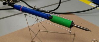
Making a homemade pulse-type electric soldering iron
Let's look at step-by-step instructions for making a transformer-type soldering iron yourself.
- Select a suitable transformer. Any power supply from the power supply of old electronic equipment with a power of 50-150 watts will do.
- Carefully disassemble it and remove the windings. You don’t have to stand on ceremony with the secondary one, but you need to handle the primary one carefully - it will become part of the product.
- Make and place on top of the primary a secondary winding from a copper busbar with a cross-section of at least 20 mm. One turn is enough; you must leave the ends of the busbar at least 15 cm long.
- For insulation, use fiberglass or heat shrink tubing.
- Attach a V-shaped piece of copper wire 1.5-2 mm thick to the ends of the bolted busbars (selected experimentally)
- Cut a handle from wood or PCB and secure the power button in it. And a transformer.
- Connect the power cable to the primary winding via a button.
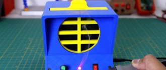
Homemade pulse-type electric soldering iron
Such a home-made pulse soldering iron, in comparison with factory samples, will look unprepossessing, but it will work no worse.
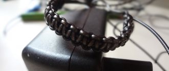
Welding pencil
This is an affordable tool that is sold in almost all specialized stores. It helps to make high-quality soldering without using a traditional soldering iron. The pencil can be stored in the house for an unlimited time; it is suitable for soldering various metals.
Instructions for using the pencil are included in the package. It's extremely easy to use:
- one end of the pencil must be heated in any convenient way;
- hold the molten end on the desired area;
- wait until the molten material cools down.
The result is a solder joint that can withstand temperatures up to 180 degrees. On average, one pencil is enough to carry out 30 rations.