Buy on Aliexpress
| Capacitive soil moisture sensor module Corrosion Resistant V1.2 (price: $0.75 ) Capacitive Soil Moisture Sensor Module (price: $0.94 ) | Capacitive humidity sensor. | |
| LM393 Soil Moisture Hygrometer Detection (Price: 0.41$) | Resistive humidity sensor. | |
| T21D Digital Multimeter RM113D 6000 Counts (Price: 15$) | Cool multimeter, like mine. Measurement of all basic quantities + flashlight, magnet, light indication, wiring detector. |
Calculations
Capacity is calculated using the following expression:
Let the plates have dimensions w = 12 mm; l = 35 mm, then the area S = 12*35 = 420 mm², and the distance between them d = 3 mm, then the calculated electrical capacitance C = 1 pF .
The geometric dimensions (area) S, as well as the distance between the plates d, does not change. To change the capacitance, it remains to change the substance between the plates, as long as it is air ε = 1 . What do you think is the relative dielectric constant of water? Sources show ε = 81 .
Full immersion in water will increase the capacity by 81 times! The calculated capacitance C will no longer be 1 pF, but 100 pF .
Thus, by smoothly immersing this homemade condenser, the capacity will also smoothly and proportionally change, which makes it possible to effectively monitor the state of humidity.
Technical characteristics of MG-44
- The measurement accuracy of the device is: +/- 1%
- The indicator device is connected by a plug connection to the sensor with a probe.
- Wide range of humidity control: 0-100%
- The measurement stability of the device is not affected by changes in the salinity of the material or its temperature.
- Length of stainless electrodes: 60 mm
- Electrode diameter: 3 mm
- The indicator block displays on the LCD display the measured humidity value and the name of the product according to the selected calibration characteristic.
The moisture meter has 99 material calibrations. The user has the ability to independently edit (add and delete) calibration points for each of 99 materials and change the name of the calibration. The microprocessor generates an approximated curve according to the specified calibration points. The minimum number of points is three. It is also possible to set the correction of the calibration characteristic (raise or lower) within +/- 5% in increments of 0.1% for each channel, you can make your own adjustment. Details about programming the device are described in the device passport.
Converting a change in capacitance into a change in voltage
By connecting a capacitor in series with a resistor, we obtain LPF ).
This results in a voltage divider where the resistance of the upper arm R1 does not change, but the capacitance of the lower arm C1 changes depending on the frequency.
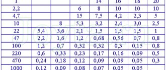
But since the signal frequency will remain unchanged, we will plot the dependence of capacitance on capacitance (C = 1-100 pF):
Thus, it is clear that as the capacitance increases (immersion in water), the resistance of the lower arm will decrease, as will the voltage drop across it, and hence the output voltage (see experimental confirmation below).
But one more thing remains - to isolate only the amplitude; this is what an AM detector . His calculation was carried out, but it did not give anything useful, so the denominations were taken the same as those of the finished one. The main point is this:
you need to select the capacitance and resistance in such a way that the capacitor has time to recharge when the signal increases, and when it decreases, it is discharged during the low level, but when the signal changes, the envelope changes.
Soldering electronics
Limit switch: operating principle and main characteristics. proven connection diagrams with your own hands!
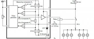
Measuring resistance in a gypsum block is actually not as easy as it seems. If you apply direct current to the electrodes in salt water, then, as you know, a chemical reaction will begin. The same thing happens in the plaster sensor and after a while it begins to show incorrect results. Therefore, alternating current is needed. The circuit below is a frequency converter to volts where the frequency depends on the humidity level. U1 is a simple oscillator. The resistance of the plaster sensor determines the frequency of the oscillator. More moisture in the sensor means less resistance. Less resistance allows C4 to charge faster by increasing the frequency. And vice versa. The less moisture in the sensor, the greater the resistance and the lower the frequency. The gypsum sensor is protected from any direct current by capacitors C5 and C6. To convert the frequency into a voltage that can be measured in a 1-wire network, the oscillator current is measured. As with many CMOS, the current is proportional to the "activity" in the circuit, which in this case is expressed in frequency. Higher frequency means higher current. The current is converted into voltage through resistor R2. U2 is the DS2760 battery monitoring chip. In our case, it is used only as an ADC. Voltage differences are measured through resistor R2 and converted in the microcircuit into values that can be read over a 1-wire network. This circuit does not operate on parasitic power, and must be supplied separately from 7V to 18V.
Testing in practice
First, the sensor itself, consisting of two pieces of foil-coated fiberglass FR-4 (70x12 mm).
*also do not forget to insulate exposed copper areas with adhesive tape
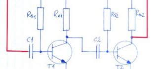
And also a miniature circuit diagram.
The signal is generated using a microcontroller (PWM, f = 1 MHz, D = 50%), of course this can be done using the same NE555 timer, but if the device already has a microcontroller, then why another MS?
Now we just connect the power (here 3.3 V), a voltmeter to the output and watch how the voltage changes when pouring water.
Very good, the readings change very smoothly and clearly.
All that remains is to digitize the readings using the ADC built into the MK and give them some semantic references, for example percentages.
Source
irrigator.ino // Connect the library for working with the display #include “QuadDisplay2.h” // give a reasonable value for the pin to which the pump is connected #define POMP_PIN 4 // give a reasonable value for the pin to which the soil moisture sensor is connected #define HUMIDITY_PIN A0 // minimum soil moisture threshold #define HUMIDITY_MIN 200 // maximum soil moisture threshold #define HUMIDITY_MAX 700 // interval between checking for plant watering #define INTERVAL 60000 * 3 // variable for storing soil moisture readings unsigned int humidity = ; // static variable for storing time unsigned long waitTime = ; // create an object of the QuadDisplay class and pass the pin number to CS QuadDisplay qd(9); void setup(void) { // start working with the display qd.begin(); // pump pin to output mode pinMode(POMP_PIN, OUTPUT); // display 0 qd.displayInt(); } void loop(void) { // read the current soil moisture sensor readings int humidityNow = analogRead(HUMIDITY_PIN); // if the current soil humidity readings // are not equal to the previous request if(humidityNow != humidity) { // save the current humidity readings humidity= humidityNow; // and display the humidity readings on the display qd.displayInt(humidityNow); } // if a specified time interval has passed // and the humidity sensor value is less than the permissible limit if ((waitTime == || millis() - waitTime > INTERVAL) && humidity < HUMIDITY_MIN ) { // turn on the pump digitalWrite(POMP_PIN, HIGH); // wait 2 seconds delay(2000); // turn off the pump digitalWrite(POMP_PIN, LOW); // set equal to the waitTime variable // the value of the current time plus 3 minutes waitTime = millis(); } }
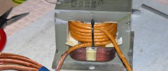
A more practical sensor made of galvanized plates
Covered with a layer of adhesive tape.
With dry ground, the output is approximately 1.5 V.
After super-abundant watering 0.75 V.
Scaling the solution
We described the solution for one plant. But usually several plants need to be watered. In addition to the obvious solution - connecting several pumps and humidity sensors to Arduino - there is a simpler and cheaper one. It is enough to make holes in the tube that comes with the pump with an awl at a distance of about 30 cm and stick pieces of rods from ordinary ballpoint pens into these holes. It will look like this:
Pots of flowers at home often stand in a row on the windowsill. You just need to place the tube on the pots so that the holes in it are one per pot. Now our device can water several pots at once. However, in this case, you can decide on the need for watering only one pot at a time. However, usually the pots are about the same size and therefore dry at about the same speed. You can also combine the two solutions, dividing all the pots into groups of approximately equal sizes.
Automatic watering system (the simplest version)
I bought a small water pump, it works well and is good for testing.
Pump control via a switch (field-effect transistor IRLML2502 ) with a 1 kHz PWM signal.
After calibration is completed, the program will turn off the pump when the voltage drops below the lower threshold (0.75V) and turn it on when it crosses the upper threshold (1.4V).
Flaws
The main problem with such sensors is their fragility. Sensitive elements are immersed in the soil, electricity is applied to them, and this leads to gradual oxidation and failure: oxides quickly destroy the metal. The probe begins to give incorrect readings, and over time it stops working completely.
Some manufacturers eliminate this drawback by coating the contact surfaces of the probe with immersion gold and other materials. But modules with such coating are more expensive.
There is also a software method of protection - do not apply voltage constantly, but only from time to time, measuring humidity at certain intervals. This can seriously extend the “life” of the hygrometer. Some enthusiasts are implementing projects that are alternative to standard sensors - for example, on graphite rods.
Application areas
Soil moisture
The most obvious application would be to determine soil moisture in a flower pot or just on the site.
Thus, you can integrate this sensor into an automatic plant watering system.
Presence of rain
To detect rain, you can also use a sensor of this type; simply place a sponge between the plates and collect the drops using a funnel.
Thus, during rain, the foam absorbs water, the capacity increases, and after the rain stops, the residue will go down, and after a while it will become dry again.
Water level in tank
Having a small (or large) supply of water in the tank is convenient to check its level from a distance, because usually the container is located somewhere in a hard-to-reach place at a height.
If the container is metal, then it can act as one electrode. If it is plastic, then you will have to make it, but it is not that difficult.
Touching the body
In one of the devices, the principle outlined above was used to detect touch to the human body, an example is below.
*this is an electronic thermometer; look at the upper right corner
Automation operating principle
In automatic watering systems, the rule is usually “water it or don’t water it.” As a rule, no one needs to regulate the water pressure. This is due to the use of expensive controlled valves and other unnecessary, technologically complex devices.
Almost all humidity sensors on the market, in addition to two electrodes, have a comparator in their design. This is the simplest analog-to-digital device that converts the incoming signal into digital form. That is, at a set humidity level, you will receive one or zero (0 or 5 volts) at its output. This signal will become the source for the subsequent actuator.
For automatic watering, the most rational option would be to use a solenoid valve as an actuator. It is included in the pipe break and can also be used in micro-drip irrigation systems. Turned on by supplying 12 V.
For simple systems operating on the principle “the sensor is triggered - the water flows”, it is sufficient to use the LM393 comparator. The microcircuit is a dual operational amplifier with the ability to receive a command signal at the output at an adjustable input level. The chip has an additional analog output that can be connected to a programmable controller or tester. An approximate Soviet analogue of the LM393 dual comparator is the 521CA3 microcircuit.
The figure shows a ready-made humidity relay along with a Chinese-made sensor for only $1.
Below is a reinforced version, with an output current of 10A at an alternating voltage of up to 250 V, for $3–4.
Total
The advantage of a capacitive sensor over just two bare electrodes is the absence of an electrochemical reaction (electrolysis), in which substances will be restored at the contacts (from solution) and spoil the soil, and in addition they will themselves corrode. Of course, you can slow down this process very significantly (rarely poll the sensor), but still.
The copper pads are protected by a mask, but will it be durable enough in harsh conditions? The possibility of an additional coating with a layer of varnish/paint is being considered.
Manufacturing a capacitive sensor is easy using PCB manufacturing techniques, especially when the other components are located there. If it must be large, then we use scrap metal.
Since the readings obtained depend on the parameters of the sensor, it requires calibration.
Soil moisture determinant for indoor plants
Without special measuring instruments, it is difficult to determine the optimal timing and norms of water consumption for irrigation.
One way or another, for this it is important to know as accurately as possible what the soil moisture is (including as a percentage of field moisture capacity)
In J. Jenik's book “Fundamentals of Gardening” there is a table that can help a gardener evaluate “by touch” the moisture content of medium- and light-textured soil.
It follows from it that dry soil is powdery, its field moisture capacity is practically equal to 0.
Sometimes the soil crumbles and does not form a ball. This means that it has critical humidity - its field moisture capacity is less than 25%.
When the soil rolls into a lump, after several throws it crumbles, this means that the field moisture capacity is 25-50%, the soil is moderately moist and the time for watering has arrived.
Keep in mind: on sandy soils, rolled clumps are looser and more brittle at any of the listed moisture levels.
At 50-75% of field moisture capacity, the degree of soil moisture is good. At this time, the soil rolls into a ball. And even if you throw it five times, it does not crumble. When you squeeze the soil, it will slightly stick to your hands.
Excellent degree of humidity at 75-100% field moisture capacity. It can be judged by the fact that the soil rolls into a strong lump, is very pliable when squeezed, and easily sticks together. If you squeeze the soil harder, a rather large lump will stick to your fingers.
And it’s really bad if the soil is too wet, above the field moisture capacity. Sometimes, if you squeeze hard, you can squeeze out a little water from the lump. Watering in this condition is not only wasteful, but even harmful.