IR 8(632) for 2002
A hydraulic ram is especially good in a local water supply, for example on a small farm near a rural pond. But it was also used in large ones - to power the fountains at Versailles, for example. In the nineteenth and early twentieth centuries. These machines were produced in large series in England, Germany, and the USA. A specialized one worked in Moscow back in the early thirties. In some places this ancient technique still works. But - rarely: advances in electrification and some disadvantages of the hydraulic ram have undermined the competitiveness of this pump.
However, today electricity is becoming increasingly more expensive. And far-sighted business executives remembered the hydraulic ram. But the known designs are inconvenient in many places: it is necessary to drain a significant part of the water flowing through the pump. This means that a drainage location is required below the pump location. And it itself must be below the water level in the source. These conditions can only be met at a dam or on a mountain river. A dwarf dam on a small river will also work. But what to do on a large bank, where it is impossible to build a makeshift dam?
M. Burangezlov’s “underwater hydraulic ram” does not need a dam. He doesn't need a drain either.
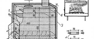
To start the operation, water is supplied from the starting tank 1 to cylinder 2 under pressure, greater than the speed pressure of the river flow. For this purpose, the container is located quite high. Piston 3 moves the rod 4 and the shock valve disk 5 attached to it to the left. A cam mechanism mounted in the rod rotates disk 6 so that the holes in both disks coincide, as a result of which the resistance to the flow of river water through the hydraulic ram decreases. The movement of the rod will stop when the stop 7 presses on the rack 8 of the valve 9 control mechanism. It will open, the pressure in the cylinder will drop, and the rod will move to the right under the action of high-speed pressure. In this case, the cam mechanism will rotate disk 6 around the axis of the rod so that the holes in the disks will close and the valve resistance will increase, and the speed of water flow and movement of the valve with the rod will be equal. The movement to the right will end with disk 5 hitting the edge 10 of the supply pipe. The flow will instantly close and a water hammer will occur. The dynamic water pressure will open the check valves, water will flow into the air cap 11 and then into the consumer network and into the hydraulic accumulator 12, and then into cylinder 2. Under the influence of this pressure, the piston will begin to move to the left - the process will be repeated and will be repeated automatically without the participation of the starting container 1, which will be replenished when cylinder 2 is filled.
This machine does not need to drain “excess” water, which not only increases efficiency and ease of use, but also makes the machine almost universal - it can work on any river. The faster the flow, the more efficient the pump or the smaller it is for the same performance. The installation of a water supply system with a hydraulic ram requires caution: there is no need to install it anywhere. On the quietest river there are rapids where the current is stronger than average. There is a place for hydraulic rams. Operable all year round if installed below the freezing point of the river.
The performance and efficiency of the device can be slightly increased if the receiving pipe is replaced with a confuser, then the flow rate through the shock valve will increase.
Pat. 2137949. Burangezlov M.K.
129515, Moscow, Academician S.P. Korolev St., 13. OJSC "Institute GINTsvetmet". Patent attorney Malysheva G.K.
Hydraulic ram design
Conventional pumps consist of a pumping device (closed impeller, piston, membrane), an activator (internal combustion engine, electric motor, other drive), a pipeline and a valve system. The design of a hydraulic ram pump is extremely simple; its uniqueness lies in the fact that the activator and piston are the agent itself (water). Its design is notable for the fact that it has no mechanical moving parts (except for two primitive valves), and does not use fuel and lubricants and areas under constant pressure.
The base of the pump is a solid tube with three elbows, which can be assembled from ordinary fittings and pipe available at any plumbing store.
First withdrawal. A supply pipe (feeder) is connected to it; we will talk about it separately.
Second branch. A check valve, an expansion tank with soft walls and an outlet pipe are connected to it through nipples and couplings. A plastic bottle is quite suitable as an expansion tank; on factory models, full tanks are installed in a metal case with a rubber membrane.
Third branch. The main element must be installed here - a flow-through hydraulic valve. This is an element of shut-off valves that blocks the flow of water when pressure increases critically. Its operation is regulated by a spring. Such valves up to 1.5″ can be found in the store, but with a larger diameter their cost can be quite high (20 USD and more). If the task is to create a pump for real household needs for a large volume of water, it is better to make this valve yourself.
Assembling a pump with a homemade valve - step-by-step video
Kinds
Scientists are making attempts to eliminate the shortcomings of the classic pump. For example, the task is set of how to make a hydraulic ram work in standing water, which is contained in ponds, lakes and wells. This question was asked by V.V. Marukhin and V.A. Kutienkov. They decided to change the existing design - they installed a baffle valve in front of the pressure valve, and plugged the drainage area.
In this case, there is no need to ensure that all the water exits the discharge pipe. It becomes possible to immerse the device in standing water. In this case, the pond or lake itself becomes a feeding reservoir, and the slope of the discharge pipe is no longer necessary.
Hydroram with one larger capacity tank
It can be laid horizontally, since the operating pressure is created by the depth of the pump. It is impossible to completely remove the discharge pipe in the Marukhin hydraulic ram. Its purpose is to form a directed flow, isolated from the general water mass and giving a hydraulic shock.
The authors, using calculations, established that the minimum depth required for the operation of such equipment is 15 meters. Only under such conditions will pressure act that will force the flow to move and provide water hammer.
Another inventor, M. N. Burangulov, presented to the scientific community his version of an underwater hydraulic ram - it differs from its analogues in its increased productivity. Water hammer is used to the fullest here. This effect is achieved through a special bumper valve device.
It consists of two disks, one of which is rigidly fixed, and the other has the ability to rotate around its axis. Additional structural elements have been added here - a rod, a piston. In such a system, the rebound valve closes instantly, which makes the impact from the water column more powerful, and the efficiency of the pump as a whole increases.
Rogozin's hydraulic ram is another type of device for collecting natural liquid. The inventor's developments were particularly successful in the USSR. Rogozin proposed combining a hydraulic ram with a turbine to which an electric generator is connected. In this case, the water-lifting device also becomes a source of energy.
A turbine connected to a hydraulic ram operates in a flow in which it is not capable of functioning independently.
But here special attention should be paid to ensuring that the water passing through the baffle valve immediately makes room for the newly approaching portion of liquid
What you need to make a hydraulic ram with your own hands
You won't need to spend a lot of money to make such a product. The main parts here will be two check valves. Their diameter depends on the required water pressure. In today's example, half-inch valves and pipes will be used, but if, say, watering a garden is required, you will have to select thicker elements.
In addition to the valves, you need to prepare plastic pipes, a pair of tees, an elbow, a ball valve and a plastic bottle that will be used as an expansion tank.
PHOTO: YouTube.com For example, check valves with a diameter of half an inch will be used
Altai Mowgli, the path from taiga to civilization
The story of this young man caused a lot of noise at one time. By the age of 18, he did not have any documents, because his parents, even before his birth, decided to hide from civilization in the Altai forests. The guy did not attend kindergarten, did not go to school, however, he could not be called illiterate; he wrote competently and read fluently.
Until some point, Ojan Naumkin was quite happy with his forest life, but later he decided to make drastic changes.
How and why a hydraulic ram works
The main feature of this pump is that it uses the kinetic energy of water that is already in the flow. That is, to supply water to a height, a level difference is necessary. It can be minimal - 0.5 m, but the higher this figure, the more efficient the pump. We deliberately do not provide a hydraulic calculation - it is extremely complex and comes down only to the optimal proportion of the height difference between the water intake point, the working part of the pump and the upper drain point. Since this device will be installed in specific conditions, it is reasonable to determine all values locally.
Water entering the feeder, under the influence of gravity, tends to the lowest point, creating excess pressure to which the hydraulic valve responds. At the moment it is triggered, water is blocked in a closed system and a water hammer phenomenon occurs, which pushes water through the check valve into the expansion tank. The elastic walls of the tank accumulate excess pressure from water hammer, but not in water (it is incompressible), but in air. This pressure pushes water through the outlet channel (hose, pipe), and the check valve prevents the pressure from equalizing.
The principle of operation of a hydraulic ram pump in the video
After the pressure in the expansion tank is released, the hydraulic valve opens again and the cycle resumes. Water supply occurs in pulses. Many have already guessed that the operation of the pump is made possible due to the difference in the density of the media - incompressible water and air, which easily accumulates pressure. The entire force of the water hammer goes into compressing the gas (air) in the expansion tank, which then supplies water to the top.
Job
Do-it-yourself wigwam: we make children's huts for games
Initial state: knock valve B is open and held in this position by a spring or weight, etc. The force of this spring exceeds the force of static
column of water in the supply pipe to
the closed
baffle valve. Check valve B is closed. The air cap is filled with air.
Water flows through supply pipe A, accelerating to a certain speed, at which break valve B, carried away by the flow of water, overcomes the force of its spring and closes, blocking the drain. The inertia of water abruptly stopped in the supply pipe creates a hydraulic shock - a sharp jump in pressure, the magnitude of which is determined by the length of the supply pipe and the flow rate. The pressure of the water hammer overcomes the pressure of the water column in the outlet pipe D, the return valve B opens and part of the water from the supply pipe A passes through it and enters the outlet pipe but, mainly, into the air cap D, since the inertia of the mass of water in the outlet pipe D prevents this fast, impulse entry. The water in the supply pipe is stopped, the pressure drops and reaches a static value, the return valve closes, and the pressure relief valve opens. The water in the supply pipe begins to move, gradually accelerating, and at this time, under the pressure of the air pressed in the air cap, the portion of water entering it is forced into the outlet pipe. Thus, the system returns to its original state and begins a new cycle of operation.
Operating principle[edit | edit code]
This mechanism operates using a supply of mechanical work contained in the water flowing through the pipe. In the original Montgolfier apparatus, built at Saint-Cloud, near Paris, water flows through a long pipe AB {displaystyle AB} (Fig. 1) from a low pond and is free to flow out over the edge K {displaystyle K} as long as the valve V {displaystyle V} is omitted.
Rice. 1. Montgolfier hydraulic ram
From the moment the water filling AB {displaystyle AB} has the opportunity to flow, the work of gravity will go to increase its speed to some maximum value determined by the height h {displaystyle h} of the water level in the pond above the hole K {displaystyle K}, dimensions and properties (see below) of the pipe AB {displaystyle AB}. At the same time, the hydraulic pressure of water on the lower surface of the valve V {displaystyle V} will also increase, the weight of which is chosen so that it rises and closes the outlet as soon as the speed of the water in the pipe reaches its maximum value. At this moment, the hydrostatic pressure of water on the inner surface of the pipe AB {displaystyle AB} and its continuation CS {displaystyle CS} will begin to increase, since the movement of water will slow down until the entire supply of work contained in its mass in the form of manpower is spent on the stretching of these walls, the compression of the water itself and internal friction. But part of these walls is made movable: in the bell-shaped appendage S {displaystyle S} a certain amount of air is closed by water and valves W {displaystyle W} are placed, opening into a bell R {displaystyle R}, which also contains air above the water and is equipped with a riser pipe DE {displaystyle DE} . Therefore, after the valve V {displaystyle V} is closed, the living force of the water begins to compress the air in S {displaystyle S} until the valves W {displaystyle W} rise; then the water will enter R {displaystyle R}, partly compress the air in it, and partly rise through the pipe DE {displaystyle DE} to a height H {displaystyle H}. All this will soon consume all the living force of the water, the pressure in R {displaystyle R} will outweigh the pressure in S {displaystyle S}, the valves W {displaystyle W} will close, V {displaystyle V} will open, and the whole process will begin again. The increase in pressure will be greater the faster the valve V {displaystyle V} closes and the more inflexible the walls of the vessel containing the water in motion. They carefully try to avoid such a “hydraulic shock” when installing water pipelines so that the pipes do not burst, which is why Montgolfier designed the cap S {displaystyle S}; the elastic compliance of the air contained in it weakens the force of the blow; the air in the cap R {displaystyle R} serves as a regulator for the pipe DE {displaystyle DE} and maintains the movement of water in it during the period when the valves W are closed. At increased pressure, more air dissolves in water than at atmospheric pressure, so the amount of air in S {displaystyle S} and R {displaystyle R} would decrease during continuous operation. To replenish this loss, a valve H {displaystyle H} is used, opening inward: as soon as the valves W {displaystyle W} are closed, the elasticity of the air in S {displaystyle S} will cause the water in CBA {displaystyle CBA} to flow back; with the acquired speed it will pass its equilibrium position and produce for a very short time under S {displaystyle S} a pressure less than atmospheric. At this point, some air enters through H {displaystyle H}.
There are ready-made types of rams on sale, from the English companies Dulas, the French Decker, etc. When tested at the Paris Conservatory of Arts and Crafts, rams made by Decoeur gave a useful effect of 0.6 to 0.9. Figure 2 shows the features of its device: both valves are located one above the other and are equipped with springs and screws to adjust their tension during operation, changing the number of blows from 40 for a fall of 0.3 m to 220 for a fall of 2 m; the lifting height in all experiments was 9 m 15 cm.
Rice. 2. Decker hydraulic ram
When air is admitted through the side valve, not shown in Fig. 2, the ram operates without noise, but the useful action and the highest possible lifting height are reduced. The good results of the action of the Ram are so dependent on the timely closing of the outlet ("stop") valve that for large machines Pearsall has found it advantageous to construct for this purpose a special machine driven by compressed air from under the hood. This type of ram operates completely smoothly, gives a high efficiency and can be built in large sizes. On the same principle, Persall constructs a hydraulic ram to produce a stream of compressed air.
Feeder and hydraulic valve
These two elements are the main ones in the design that you plan to create yourself. The entire operation of the unit depends on their size and design.
Feeder
It is a closed channel connecting the water intake point and the water hammer point. Ideally, this is a long, level pipe located on a slope. The water in the pipe is the very piston that creates excess pressure - the cause of water hammer. Therefore, the larger the cross-section, the more powerful the ram will be. The diameter of the feeder pipe should be within reasonable limits - from 50 to 150 mm. This value must be correlated with the diameter of the remaining channels of the system and the required feed height.
We recommend installing a socket in the intake part of the feeder for better water capture.
Optimal ratios of hydraulic ram pump diameters
| Feeder, mm | System, mm |
| 50 | 16 |
| 100 | 32 |
| 150 | 32–50 |
In the latter case, with a feeder length of 10 m and a drop of 1.5 m, water will be supplied to a height of 10 m at a speed of about 1500 l/hour.
Hydraulic valve
The factory model of this device may be expensive due to the material, gaskets and spring set to a certain pressure. In our case, when we use free energy, which simply does not make sense to save or take into account, the very fact of blocking the flow of water is enough. A self-made hydraulic valve is quite suitable for this.
Pump with homemade hydraulic valve - installation video with comments
The ideal place to install such a pump is river rapids with their significant drops or streams.
History[edit | edit code]
In 1772, the Englishman John Whitehurst invented and built a “pulsating engine,” the prototype of a hydraulic ram, and published its description three years later. Whitehurst's device was manually controlled. The first automatic hydraulic ram pump was invented by the famous Frenchman Joseph-Michel Montgolfier together with Ami Argand in 1796. In 1797, with the help of his friend Matthew Boulton, Montgolfier received a British patent for his invention. In 1816, Montgolfier's sons patented a modified version of this pump.
In the USA, the hydraulic ram pump was first patented by J. Cerneau and SS Hallet in 1809. In 1834, the American H. Strawbridge began producing hydraulic ram pumps.
In 1930, Professor S. D. Chistopolsky, in his work “Hydraulic Ram,” published a method for theoretical calculation of such devices, based on the theory of water hammer created by Professor N. E. Zhukovsky in 1897-1898.
Water hammer or how to make a free pump using water energy
In this article we will talk about how to create a pump that does not require fuel or electricity to operate.
The article contains a description of the operating principle of the device, the main design elements, as well as a video of the assembly process of the basic model of the ram pump. You will learn how to assemble it yourself. Hydraulics is a science as ancient as water itself. The laws of hydraulics apply to absolutely any fluid, and we will look at how to use these laws to organize a pump or pump using kinetic energy.
The prototype of a pump based on the action of water hammer was created in France back in the 17th century by the inventor of the hot air balloon Montgolfier. Almost simultaneously with it, inventors in England, the USA and Germany patented an identical design. In Russia it received the sonorous popular name “hydroram”.