Why do I need it?
If you have no doubt about the necessity and usefulness of this device, then you can skip this point.
For the rest, I would first like to talk about the prerequisites for the creation of this device. At all times, programmers and designers tried to create a convenient and user-friendly interface so that the user could work with the application using a mouse and keyboard without unnecessary problems, so why do we need another manipulator? Well, let's look a little into history, or more precisely, at the beginning of the 18th century, when such a musical instrument as the piano was invented. As you know, this word literally translates as “loud-quiet,” but few people think that the clever Italian master obtained such an instrument by actually “pedaling” the then existing harpsichord, which made it possible to control the volume of the sound to some extent, without taking your hands off the keys.
Many examples can be given. The car has pedals so you don't have to throw the steering wheel if you need to add gas. The drum kit also has pedals to hit the bass drum and cymbals. What can pedals do when using a computer? Well, for example, you can set some hot key combination, or even add a key that doesn’t exist, like turning the sound on and off. Pedals can help if your hands are full: I myself play the guitar, sometimes with accompaniment, it would be very convenient for me to wind the backing without constantly trying to reach the keyboard. And, finally, controllers can provide completely inhuman capabilities in games: it would be cool to build your entire base in a strategy game with one click or destroy enemies at a speed of ten beats per second in shooters, wouldn’t it?
In general, I hope I have convinced you, which means it’s time to proceed directly to the development itself.
master class with photo and video lessons
On the eve of any holiday, every woman thinks about a gift for her beloved man and wants to please him. Particular attention is always paid to handmade gifts. A candy bar would be a great option at the moment as it is a masculine gift that every woman can give. And delicious sweets will be a pleasant sweet bonus, since it is from them that this wonderful, beautiful and very tasty masterpiece will be created.
Master class: DIY candy steering wheel
This master class is quite simple and will show you how to make such a steering wheel from candies and other materials in a short time. It is enough to arm yourself with everything you need and be patient.
Materials and tools
- Penoplex 2 cm wide and 35 cm in size;
- Black paper;
- Chocolate candies 500 gr;
- Beautiful braid 2 cm wide and 2 m long;
- Stationery knife;
- Scissors;
- Pen;
- Ruler;
- Hot glue gun;
- Cardboard;
- Double sided tape;
- Audi logo sticker;
- Dishes.
The process of making a steering wheel from candies with your own hands
- Start work with the workpiece. To do this, you need to take penoplex, place a large round wide plate of large diameter on it and circle it with a handle. The result is a circle.
- Take a smaller plate, apply it to the center of the circle and trace it with a pen. The width of the indent strip should correspond to the size of the candies, so the size of the plates must be chosen carefully. Often, not only plates are used as a template, but also pots and other containers that are round in shape. The approximate distance between circles will be 2 cm.
- Again, take a larger plate and apply it to the workpiece in such a way as to outline a figure that forms a crescent. It will be located in the middle of the steering wheel. A similar action is performed with the plate, moving 2 cm down.
- A few more details are drawn by hand with a pen so that the blank looks like a real steering wheel.
- Using a stationery knife, cut out a blank from penoplex.
- When the blank for the steering wheel is completely cut out, it needs to be glued all over. To do this, take paper, scissors and a glue gun.
- The entire surface of the workpiece is covered with hot glue, but you should work in stages, because heated silicone glue hardens quickly. The glue must be applied in a thick layer.
- The paper is glued to the workpiece so that at least 1 cm remains at the edges, which will be used for folding. This is done so that the seams are not visible. Excess paper is cut off with scissors.
- Turn the workpiece over to the reverse side and cut the paper 1 cm larger than the size of the steering wheel.
- The ribs of the steering wheel are coated with hot glue and glued one by one with the paper that was left when cutting, 1 cm in size.
- Using scissors, cut out individual pieces of paper in the middle of the steering wheel, leaving 1 cm for the fold.
- After cutting out all the parts from the paper, glue the remaining pieces of paper for folding in the middle of the steering wheel using hot glue. To do this, coat the inner ribs of the steering wheel with hot silicone glue, fold the paper and glue it. All edges must be covered with paper so that the penoplex is not visible. At this stage, one side of the steering wheel is already ready.
- Turn the steering wheel blank over to the opposite side and glue it with paper in the same way as the front part.
- When both sides of the workpiece are glued, you need to pay attention to ensure that all seams and joints are in the middle, because you need to glue the ribbon on top. Thanks to this tape, all seams will be closed after gluing. The tape should also be glued to a glue gun.
- The inside of the steering wheel is taped in the same way.
- When the blank for the steering wheel is completely ready, proceed to the stage of gluing the candies. It is recommended to first place all the candies on the steering wheel blank in order to create the desired composition and visually distribute all the candies on the steering wheel.
- Before gluing candies, it is worth considering that the candies themselves melt from hot glue. Therefore, before gluing the candy to the steering wheel, you need to cut out a small strip of double-sided tape and a strip of cardboard. A piece of double-sided tape is glued to each candy, onto which a piece of cardboard is attached. And only after this can the candy be glued with hot glue by dropping a drop of glue onto a piece of cardboard that is glued to the candy.
- The entire steering wheel is covered with candies, after which a sticker with the Audi logo is glued in the center of the steering wheel.
- The result was a wonderful and tasty candy steering wheel.
You can use various photos that will allow you to recreate such a steering wheel from candies of any brand and model. Any man will like such a sweet gift and will not go unnoticed. You can use any candies for such a gift, preferably those that are preferred by the person for whom this sweet gift is being created.
Required Resources
- Actually, the pedals.
Some difficulties immediately arose here due to the fact that I could not come up with a name for such a pedal.
All I knew was that similar things are used in sewing machines. In general, at the request of electric pedal,
I still managed to find what I needed on Aliexpress, and without thinking twice, I ordered 3 pieces. - Controller.
The pedalboard should emulate the operation of a keyboard and, possibly, a mouse to be able to connect to a PC without unnecessary drivers. The Arduino Pro Micro board is perfect for this, which, although it does not have some pins, is made as compact as possible. We go to the same Aliexpress and buy the Chinese version of this miracle. - Wires.
To place 3 pedals under the table, you need at least a four-wire wire at least a meter long. Here, I think, there should be no problems. - RGB LED and button.
The first one is needed to indicate modes, and the second one is needed to switch them. - Well, of course, we need an Arduino IDE, a soldering iron and straight hands.
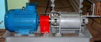
Pedals
The base of the module is made similarly to the steering wheel module from 12mm plywood with a hardwood cross member (3) for attaching the return spring. The flat shape of the base serves as a footrest. The pedal stand (8) is made of a 12mm steel tube, to the upper end of which the pedal is bolted. A 5mm rod runs through the bottom end of the post, which holds the pedal in mounting brackets (6) screwed to the base and made from angle steel. The crossbar (3) extends across the entire width of the pedal module and is securely (must withstand full extension of the springs) glued and screwed to the base (2). The return spring (5) is attached to a steel eye screw (4) that passes through the crossmember just below the pedal. This fastening design makes it easy to adjust the spring tension. The other end of the spring attaches to the pedal post (8).
The pedal potentiometer is mounted on a simple L-bracket (14) at the rear of the module. The rod (11) is attached to the drive (12) on bushings (9, 13), allowing the resistance to rotate through a range of 90 degrees.
Device diagram
Even before the packages arrived, I began creating a circuit diagram for the device. Although this is a strong word, since I only needed to connect the pedals, a diode and a button. It turned out something like this:
For pedals, I decided to allocate 4 ports PB1-PB4 at once, that is, two for the left and two for the right foot, although so far I only have 3 pedals. In addition, they are all in the same group and located in the same place. I assigned pins PD0, PD1 and PD4 to the LED, and PD7 to the button. In this case, we will not need any pull-up resistors if we use those built into the controller. True, then, when you press a button or pedal, the input level will be low, and when released, it will be high, that is, the presses will be inverted, and you should not forget about this.
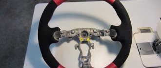
Steering wheel reupholstery at home
It is quite possible to reupholster the steering wheel yourself. With patience and time. Today in any store you can buy a special set consisting of a piece of leather, a needle and strong thread. This kit for re-upholstering the steering wheel costs around a thousand rubles and is very easy to use.
Braid stitching
- First, we put a piece of leather on the steering wheel.
- We take out a needle and thread a thread with a knot at the end through it.
- The leather from this set already has small holes along the edges of the fabric, so there is no need to pierce anything with a needle. We simply “lace up” the leather steering wheel. The easiest way to “lace”: crosswise. But you can come up with something more creative (“butterfly”, “herringbone”, etc. It all depends on your imagination).
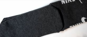
- To ensure that the leather for reupholstering is as elastic and pliable as possible, it is better to warm it up.
Full source code
He's right here
#include #include #include #define modeButton 6 struct pedal { unsigned char type;
//0 — real-time mode, 1 — trigger mode, 255 — pedal not assigned unsigned char act1[16]; unsigned char act2[16]; }; struct pedals[7][4] = { { { 255, {255}, {255}}, {255, {255}, {255}}, {255, {255}, {255}}, {255 , {255}, {255}} }, { { 255, {255}, {255}}, {255, {255}, {255}}, {255, {255}, {255}}, {255 , {255}, {255}} }, { { 255, {255}, {255}}, {255, {255}, {255}}, {255, {255}, {255}}, {255 , {255}, {255}} }, { { 255, {255}, {255}}, {255, {255}, {255}}, {255, {255}, {255}}, {255 , {255}, {255}} }, { { 255, {255}, {255}}, {255, {255}, {255}}, {255, {255}, {255}}, {255 , {255}, {255}} }, { { 255, {255}, {255}}, {255, {255}, {255}}, {255, {255}, {255}}, {255 , {255}, {255}} }, { { 255, {255}, {255}}, {255, {255}, {255}}, {255, {255}, {255}}, {255 , {255}, {255}} } }; char ports[4] = {8, 16, 15, 14}; char pos1[4] = {0, 0, 0, 0}; char pos2[4] = {0, 0, 0, 0}; char state[4] = {0, 0, 0, 0}; char oldState[4] = {0, 0, 0, 0}; char wait[4] = {0, 0, 0, 0}; void pedalAction(); char mode = 0; char curPedal; Thread pedalThreads[6] = {Thread(pedalAction, 10), Thread(pedalAction, 10), Thread(pedalAction, 10), Thread(pedalAction, 10), Thread(pedalAction, 10), Thread(pedalAction, 10)}; void setup() { pinMode(2, 1); pinMode(3, 1); pinMode(4, 1); pinMode(modeButton, 2); if (!digitalRead(modeButton)) { //Programming mode Serial.begin(9600); while (!Serial) { PORTD = 0b00000000 + (PORTD & 0b11101100); delay(250); PORTD = 0b00010000 + (PORTD & 0b11101100); delay(250); } Serial.println(F("***Programming mode***")); Serial.println(F("Write the command as ")); Serial.println(F("m - number of mode, one digit")); Serial.println(F(“p — number of pedal, one digit”)); Serial.println(F("c - command, it can be:")); Serial.println(F("\tr - read pedal info")); Serial.println(F("\tw - enter to writing mode and change pedal programm")); Serial.println(F("\te - erase pedal programm and delete it")); Serial.println(F("There are up to 7 modes and 6 pedals per mode can be configured")); Serial.println(F("Mode will be incative if there is no pedal configured in it")); while (1) { while (Serial.available()) { Serial.read(); delay(1); } PORTD = 0b00000001 + (PORTD & 0b11101100); Serial.println(""); Serial.println(F("Enter command")); while (!Serial.available()); PORTD = 0b00000010 + (PORTD & 0b11101100); delay(3); if (Serial.available() == 3) { int curMode = Serial.read() - 48; int curPedal = Serial.read() - 48; char cmd = Serial.read(); if (curMode > 6 || curMode < 0) { Serial.print(F("Mode must be in 0-6. You entered ")); Serial.println(curMode); continue; } if (curPedal > 3 || curPedal < 0) { Serial.print(F("Pedal must be in 0-3. You entered ")); Serial.println(curPedal); continue; } Serial.println(); if (cmd == 'r') { int beginAddress = sizeof(struct pedal) * (curMode * 6 + curPedal); Serial.print("type: "); int curAddress = beginAddress; Serial.println(EEPROM[curAddress++]); Serial.print("act1: "); for (int i = curAddress ; i < curAddress + (sizeof(struct pedal) - 1) / 2; i++) { Serial.print(EEPROM ); Serial.print("\t"); } Serial.println(); curAddress = beginAddress + 1 + (sizeof(struct pedal) - 1) / 2; Serial.print("act2: "); for (int i = curAddress ; i < curAddress + (sizeof(struct pedal) - 1) / 2; i++) { Serial.print(EEPROM ); Serial.print("\t"); } Serial.println(); } else if (cmd == 'w') { Serial.println(F("Enter type:")); PORTD = 0b00000001 + (PORTD & 0b11101100); while (!Serial.available()); int beginAddress = sizeof(struct pedal) * (curMode * 6 + curPedal); int curAddress = beginAddress; PORTD = 0b00000010 + (PORTD & 0b11101100); EEPROM[curAddress++] = (char)Serial.parseInt(); PORTD = 0b00000001 + (PORTD & 0b11101100); Serial.println(F("Enter act1 in DEC divided by space:")); while (Serial.available()) { Serial.read(); delay(1); } while (!Serial.available()); PORTD = 0b00000010 + (PORTD & 0b11101100); while (Serial.available()) { EEPROM[curAddress++] = (char)Serial.parseInt(); delay(1); } PORTD = 0b00000001 + (PORTD & 0b11101100); curAddress = beginAddress + 1 + (sizeof(struct pedal) - 1) / 2; Serial.println(F("Enter act2 in DEC divided by space:")); while (Serial.available()) { Serial.read(); delay(1); } while (!Serial.available()); PORTD = 0b00000010 + (PORTD & 0b11101100); while (Serial.available()) { EEPROM[curAddress++] = (char)Serial.parseInt(); delay(1); } PORTD = 0b00000001 + (PORTD & 0b11101100); Serial.println(F("Finished, don't forget to verify written data!")); } else if (cmd == 'e') { int beginAddress = sizeof(struct pedal) * (curMode * 6 + curPedal); Serial.println(F("Disabling pedal...")); PORTD = 0b00000010 + (PORTD & 0b11101100); EEPROM[beginAddress] = 255; PORTD = 0b00000001 + (PORTD & 0b11101100); Serial.println(F("Pedal disabled")); } } else { Serial.println(F("Incorrect command, please read help above")); } }; } for (int i : ports) pinMode(i, 2); pinMode(17, 1); for (int i = 0; i < 7; i++) { for (int j = 0; j < 4; j++) { struct pedal *p = &pedals [j]; int beginAddress = sizeof(struct pedal) * (i * 6 + j); int curAddress = beginAddress; unsigned char type = EEPROM[curAddress++]; if (type == 0 || type == 1) { p->type = type; for (int k = 0 ; k < 16; k++) { p->act1[k] = EEPROM[curAddress++]; } for (int k = 0 ; k < 16; k++) { p->act2[k] = EEPROM[curAddress++]; } } } } Keyboard.begin(); } int last = 0; void loop() { int current; if ((current = digitalRead(modeButton)) != last) { if (!current) { if (++mode >= 7) mode = 0; while (pedals[mode][0].type == 255 && pedals[mode][1].type == 255 && pedals[mode][2].type == 255 && pedals[mode][3].type == 255) if (++mode >= 7) { mode = 0; break; } } last = current; digitalWrite(2, (mode + 1) & 0b001); digitalWrite(3, (mode + 1) & 0b010); digitalWrite(4, (mode + 1) & 0b100); for (int i = 0; i < 4; i++) { pos1 = 0; pos2 = 0; state = 0; oldState = 0; wait = 0; } delay(50); } for (int i = 0; i < 4; i++) { if (pedalThreads .shouldRun()) { curPedal = i; pedalThreads.run (); } } } void pedalAction() { struct pedal *pedal1 = &pedals[mode][curPedal]; if (pedal1->type == 255) return; unsigned char *prg; char *pos; if (pedal1->type) { int current; if ((current = digitalRead(ports[curPedal])) != oldState[curPedal]) { if (!current) state[curPedal] = !state[curPedal]; oldState[curPedal] = current; } if (!state[curPedal]) { //act1 pos2[curPedal] = 0; pos = &(pos1[curPedal]); prg = pedal1->act1; } else { //act2 pos1[curPedal] = 0; pos = &(pos2[curPedal]); prg = pedal1->act2; } } else { if (!digitalRead(ports[curPedal])) { //act1 pos2[curPedal] = 0; pos = &(pos1[curPedal]); prg = pedal1->act1; } else { //act2 pos1[curPedal] = 0; pos = &(pos2[curPedal]); prg = pedal1->act2; } } while (1) { if (wait[curPedal]) { wait[curPedal]—; return; } else if (prg[*pos] == 250) { wait[curPedal] = prg[++*pos]; } else if (prg[*pos] == 254) { //Hold the key next to *pos Keyboard.press(prg[++*pos]); } else if (prg[*pos] == 253) { //Release the key following *pos Keyboard.release(prg[++*pos]); } else if (prg[*pos] == 252) { delay(10); //"Skip move", do nothing ++*pos; return; } else if (prg[*pos] == 251) { //Move in the program to a position in cell *pos+1 *pos = prg[*pos + 1]; return; } else if (prg[*pos] == 255 || prg[*pos] == 0) { //End of program, just a stub return; } else { //Send the keystroke Keyboard.write(prg[*pos]); } //Cyclically move forward to the cell after those commands after which this is necessary if (++*pos >= 16) pos = 0; } }
Instructions for installing the steering wheel remote control with a compatible car radio
- The glove compartment is removed.
- The heater cables are disconnected.
- The beard is removed from the panel.
- The radio is taken out, from which three wires come out - black, brown-yellow and brown-orange.
- In the connector from the radio in the left corner (yellow-green chip) there are two wires from the control panel on the steering wheel.
- Two wires from the remote control and black and brown-yellow wires from the radio are connected.
- The radio, beard and glove compartment are put in place.
Afterword
Although initially I made a pedalboard to be able to rewind recordings while playing the guitar, I personally found it convenient to use pedals for ordinary tasks, the main thing is to get a little used to such an unusual manipulator.
But here lies another problem: on the contrary, it becomes more difficult to work without your favorite pedals, since you have to remember what, where and for what to press. If you can still carry and connect pedals to the office, then at the institute it’s already more difficult to run around the offices with them. So using this device for anything other than its original purpose is at your own peril and risk. Assembled pedalboard:
Brief summary
Car tuning is unthinkable without proper steering wheel design. There are a large number of design options.
In this article we looked at the most current options. These include options for heating the steering wheel, braiding, and the use of a lazy person. How to transform your steering wheel is up to you.