October 5, 2016 ditim Home page » Grandma’s archive Views:
In one of the old issues of the Pioneer are given on how to make a simple model of an A-1 type glider with your own hands, at home.
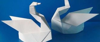
The glider model flies without a motor or propeller, smoothly descending, gliding, as if gliding in the air. It is usually launched from a handrail. A lifeline is a thick thread fifty meters long with a ring at the end. There is a hook on the glider model, and this ring is put on it.
The model must be launched against the wind. She, like a kite, rushes upward and rises to a height of about forty-five meters. At this moment, the launcher loosens the rope, the ring slides off the hook, and the model flies freely. When there is no wind, the launcher has to run a little with the rope so that the model rises to approximately the same height even in calm conditions. If the model gets caught in an updraft, it will not descend and may even begin to gain altitude.
Glider models come in different sizes. In aircraft modeling, two types of models are most common: “A-2” and “A-1”. “A-2” is a large model, with a wingspan of about two meters. Such models, if they are well adjusted, fly for two to three minutes, and sometimes they can even completely disappear from sight. But they are complex, only experienced aircraft modelers can build them.
Children, with the help of adults, can start building smaller and simpler models - “A-1”. The wingspan of this model is 1,000-1,200 millimeters, and it flies on average from one to two minutes. These models have one indispensable requirement: the total area of the wing and stabilizer should be no more than 18 square decimeters, and the weight in flight should be no less than 220 grams.
Ceiling glider for little ones
I was sorting out some information on an old propeller and found a selection of drawings for making free-flying gliders.
These aircraft models are easy to make, do not require any skills, and they are not radio-controlled models.
It's just a glider.
The drawings are scans from Polish magazines; in the original they were proposed to be made from balsa, but they would also work great from ceiling tiles.
Actually, this collection of drawings (you can download the glider drawings at the end of the article) is intended for aircraft modeling clubs for children. These still exist in schools.
You can build them just for fun with your child
The drawings are made on a scale of 1:1. Ceiling models do not require additional reinforcements; they can be made in 10-20 minutes.
If you make a glider from EPP, then it is desirable to strengthen the wing. The EPP aircraft model will be completely indestructible.
You can read about how and what to glue ceiling tiles in the article Adhesives in modeling.
If you need to bend the ceiling, then read Bending Ceiling Tiles.
If you paint the aircraft model and make it a hook for launching from a rubber catapult (an ordinary slingshot or even just a stick with a rubber band attached to it), then such models can bring a lot of fun when traveling out of town.
For example, like entertainment at a barbecue, and, I assure you, it won’t be only children who are launching it, most likely, it won’t even be them at all!
You can download drawings of free-flying gliders here.
The archive contains drawings of the following aircraft models: dc 3, F4, I 16, Il 86, minimoa, yak 23, Mustag p51, Spitfire, su 24, su 28, xf 85
To print drawings in 1:1 format with automatic division into sheets, you can use the following program
As a result, in one evening you can make the following aircraft models:
Konstantin, https://RC-Aviation.ru
Paper airplane repair
It is not always possible to achieve a smooth and straight gliding flight from the first launch. Steep turns and descents, turning the model over in the air occur either from gross inaccuracy in manufacturing, or from an incorrect push. A paper model does not last long. Rivets may fly out and the wing may tear.
The paper airplane model can be repaired. To do this, remove the unraveled pin and insert a new one into the puncture. It is better to install two studs during repairs, bending them in different directions. We will put a patch on the torn part of the wing or fuselage (Fig. 17).
If you liked our instructions on how to make a paper airplane, then come back to our website, it’s interesting with us.
Source: book “Your First Model” Pavlov A.
MANUFACTURING A GLIDER FROM CEILING TILES
MANUFACTURING A GLIDER FROM CEILING TILES
Korolikhin V.V., additional education teacher, Station of Young Technicians, Glubokovsky district, East Kazakhstan region.
This model is designed for children and teenagers who are beginners to engage in technical creativity circles.
On this model they practice skills in working, balancing the model and launching.
This model can be used for competitions.
You need to start work by making templates.
The drawings indicate: dimensions in millimeters and a scale ruler is attached, arrows indicate the direction of the fibers of the material.
When printing drawings, the dimensions may not match, so they must be adjusted to the specified dimensions.
The width and length of the parts are important; the radii of curvature can be slightly changed.
Master glue and titanium are used to connect parts.
An example of making a fuselage sidewall template.
MANUFACTURING FUSELAGE SIDEWALLS
The side panel part is longer than the ceiling slab, so we glue the workpiece together in two parts.
To do this, cut 3 pieces along the grain, 80 mm wide and long for the entire slab, cut one piece in half.
Making cuts at an angle
We place a short blank with a cutout on the long one and make markings on the long blank.
cut out a wedge.
blanks ready for gluing.
glued blanks.
mark according to the template and
Cut out the sides of the fuselage.
Finished sidewalls, left and right.
The next piece, a strip 40 mm wide and the length of the entire slab,
Curves along the contour of the sidewall.
Glue the insert, control using a square.
Cut out the next insert and glue it to the bottom of the side panel.
The upper insert, from the wide end, is bent along the contour of the sidewall and glued.
The width of the inserts in the nose section is 40mm, from the top bend of the fuselage to the tail section, gradually tapering to 20mm.
The dimensions on the side of the fuselage indicate the width of the insert at a given location. After gluing the sidewall along the contour, a package of ceiling tile plates with a hole with a diameter of 30 mm is glued into the nose part, the hole serves to balance the airframe.
After this, the second side panel is glued.
To fasten the wing in the nose, two slats are installed, oval cross-section 6 mm thick, cardboard washers are used for reinforcement.
The slats are installed 25mm from the top edge
To give the wing a profile, the blank is laid with newspaper sheets and twisted using a pipe with a diameter of 40-50 mm.
Twisting the workpiece
Wing “ears” after twisting to give profile
After giving the profile, the “ears” are cut and the edge of which the “ear” is glued to the wing is ground to give an angle.
The accuracy of the wing assembly is checked on the table by placing the wing on the table and measuring the distance from the end of the “ear” to the surface of the table, the distance should be within 100-90 mm.
A three by five mm strip is glued along the leading and trailing edges of the wing center section.
The dimensions of the wing center section are 130 mm and the entire length of the tile is cut along the grain
The workpiece is cut in half.
Ready assembled glider.
hole for balancing.
There is a hole on the side of the bow for balancing
load, after balancing it is closed with a plug.
Balancing is performed by inserting a weight into the bow through the hole. If the model lifts its nose at launch, you need to add weight, dives sharply, and reduce the weight. A properly balanced model should glide smoothly. The load is fixed with glue.
Schematic model of a glider.
glider toe.
General view
of the tail
. Schematic model.
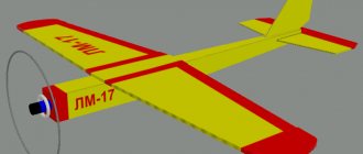
It is made on the basis of the wing from the glider described above; instead of the fuselage, a 10 by 10 mm rail with a length of 700 mm is used.
The toe, made of 10 mm plywood, acts as a weight.
A pylon is glued to the center of the wing to secure the wing to the fuselage.
The pylon is attached to the fuselage using rubber bands.
Balancing is performed by moving the wing along the fuselage.
The sock is made of plywood 10mm thick, 45mm wide, 180mm long.
Background
I had a drawing of this model for several years. Knowing that it flies well, for some reason I could not decide to build it. The drawing was published in one of the Czech magazines in the early 80s. Unfortunately, I was unable to find out either the name of the magazine or the year of publication. The only information that is present on the drawing is the name of the model (Sagitta 2m F3B), the date - either construction or production of the drawing - 10.1983 and, apparently, the first and last name of the author - Lee Renaud. All. No more data.
When the question arose of building a glider more or less equally suitable for flying in both thermals and dynamics, I remembered a drawing that was lying idle. One careful examination of the design was enough to understand that this model is very close to the desired compromise. Thus, the problem of choosing a model was solved.
Even if I have a ready-to-use drawing of a model at my disposal, I still redraw it with my own hand, with a pencil on graph paper. This helps to thoroughly understand the structure of the model and simplifies the assembly process - you can immediately develop the sequence of manufacturing parts and their subsequent installation. So construction started from the drawing board. Minor changes were made to the design of the airframe, which made it possible to fearlessly tighten the model both on the rail and on the winch.
Intensive use of the glider in the summer of 2003 showed that it is distinguished by predictability, stability and, at the same time, agility - even without ailerons. The glider behaves quite satisfactorily both in thermals, allowing it to gain altitude even in weak currents, and in dynamic conditions. I note that the model turned out to be too light, and sometimes additional loading of the airframe is required - from 50 to 200 grams. For flights in strong dynamic currents, the glider has to be loaded more - by 300...350 grams.
The model can be recommended for beginners only if the training is carried out together with an instructor. The fact is that the model has a relatively weak tail boom and bow. This does not cause any problems if you at least know how to land a glider, but the model may not withstand a strong blow to the ground with its nose.
Airframe drawings (AutoCAD 2000)
green_plane.zip 267.41 kB
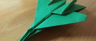
Coach from the ceiling | Model aircraft drawings
To assemble the model, you will need the following electronics: Servo 5g (2 pcs.) Motor 2205 kv1400 Speed controller 10A Battery 2s1p 800mAh 20C Propeller 9 × 4.7 SF
I’ve never built an airplane with a wing from a bent ceiling, so I decided to practice on this trainer. I assembled the fuselage, without glue yet. Everything comes together like a construction set, it’s very nice to build.
Assembled the wing. It turned out to be quite acceptable. On UHU Por it comes together very quickly. I glued the tail in and attached the elevator. I glued loops from packing tape into the ailerons; I like this method much better than hanging it on tape. The boars were cut out on a machine.
The flight weight was 188g. The plane is not covered with tape and will quickly get dirty when landing on its belly, so I decided to add landing gear. The chassis was not originally planned and there are no fastenings for them. Using threads, I attached the landing gear to a platform made of light plywood, which I secured to the fuselage with double-sided tape. The mount is easy to remove; during a hard landing, the landing gear will detach without breaking out the fuselage elements.
Flew around. Take off by hand, land on the landing gear. It flies smoothly, as befits a trainer, and allows you to turn the rudders mindlessly in any direction =) There were gusts of wind, but it’s okay, it endures everything. He glides well and sits down almost on his own. From aerobatics, you get forward and reverse loops, rolls, and inverted flight. I highly recommend this trainer for beginners.
In the evening I went to fly again and started chasing crows. During sharp maneuvers, the wing jammed behind the plywood connector. I finalized the drawing and added balsa shelves 250x12x2 to each console at the top and bottom. The wing will have to be redone. The spars with balsa turned out to be very rigid, now the wing will not break.
The new wing turned out to be 3g heavier, but it does not bend in flight, while the old one was noticeably bending. The trainer, who is a trainer in everything, tried painting foam plastic and adhesive tape with acrylic. I made the mask with duct tape. The paint ran a little under the mask, but it turned out okay. The paint also adhered well to the tape.
Step-by-step instructions for a flying toy for beginners
The interesting thing is that almost any plane can fly a sufficient number of meters above the ground, it can be 10,000 or even more than 1,000,000, the most important condition is, depending on what height it will be launched from and whether there will be wind outside and how it will pick it up.
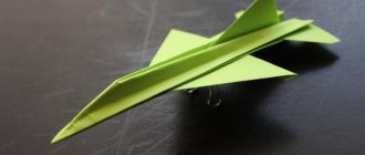
If you want your airplane to never fall over, then use this scheme. This toy will show you a uniform and very fast flight. You yourself will be very amazed.
If you love this type of air transport with large wings, then fold this type of airplane.
You can build it with a blunt nose, there will be no collisions.
Well, if you don’t understand diagrams and instructions at all, then watch this step-by-step video from the YouTube channel:
Airframe construction diagram
The construction scheme is simple. To get started, download the File with wing, tail and bulb templates. We print the file on the printer, trim each sheet on one side, follow the marks on the edge of the sheet and glue the sheets together to form the outline of the wing. We cut out templates for the stabilizer wing, fin and nose thickening (5 pieces). We glue two wing blanks together.
Blanks, tools, materials Sheets of airframe parts template Gluing airframe template sheets Cutting out templates Airframe parts templates
Preparing a set of foam airframe parts
We place the stencils on a sheet of ceiling and trace their contours. We cut out the blanks along the outlined contours with a stationery knife, see photos and videos.
Transferring the contours of parts Contours of airframe parts Cutting out airframe parts Airframe parts If you don’t have a stationery knife, you can use a kitchen knife, but it must be sharpened, such as an electric sharpener.
We give the stabilizer and wing an aerodynamic profile. To do this, we use a block of wood wrapped in sandpaper. Watch the process in the video. Using a block, we round the leading edge of the wing and thin the trailing edge. To give the wing a real concave glider profile, the latter is rolled on the smooth edge of a board or table. The process is shown in the video. To begin with, it is better to practice on a small piece of foam. And then on the stabilizer. And after gaining the skill to roll the wing. For stable flight of the glider, the wing must be given an arched profile with its increase at the wing tips. The profile is also formed by rolling. The wing after shaping the profile must be symmetrical! The keel profile should be symmetrical - oval at the leading edge and thinner towards the rear edge.
Removing the shiny film Wing profile Forming edges Profile rolling Arc wing profile
Manufacturing of the airframe fuselage
Fuselage. In this glider model, the rail is cut from a pine block with a circular saw and brought to the desired section of 7 by (4-5) mm with sandpaper. Rail length 400-450 mm. The nasal thickening is glued together from five pieces. Before gluing, ceiling tiles with a pattern must be sanded to remove the thin film of the pattern. PVA glue does not stick to the film. The thickening blanks are covered with glue, slightly dried, joined together and tightened with clothespins or pins. The fuselage rail is glued into the nose thickening.
Gluing the bulb Drying the glue
Making the tail
Tail unit. We clean the place where the keel is glued to the stabilizer from the film, cover it with glue and glue the keel. The gluing must be symmetrical! The direction of flight depends on this! After gluing the fin, the empennage is glued to the fuselage. To fix the position, you can use tailor's pins or masking tape.
Assembling the empennage Gluing the empennage
Glider wing mount
The glider wing must be mounted on the fuselage. For this, a pylon made of foam strips is used. The angle of installation of the wing to the fuselage is 1-2º. The wing is glued to the fuselage strictly symmetrically. Do not forget to grind off the shiny film of the pattern on the foam ceiling.
Glider wing pylon Symmetry of wings and tail Bulb weighting option
Adjusting, tuning and flying the model
First, the center of gravity is set at about 1/3 of the distance from the leading edge of the wing. The center of gravity is established by weights on the nose of the glider made from scrap materials or plasticine (see here about the center of gravity). It is necessary to achieve stable gliding of the glider model with a slight throw by moving the center of gravity closer to the center of the wing. Once configured, you can move on to the next step. Launching the glider at an angle of 30-45° to the horizon with increasing throw force. This will require additional tuning of the model. A tuned model in a large room can stay in flight for up to 20 seconds (flight in a circle, adjusted by turning the edge of the keel). And when launched in a field under favorable conditions and wind, up to several tens of seconds. And launching from a mountain or tall building will give you minutes of flight
Be careful - the model may be lost!
Characteristics
The main characteristics of the airframe are:
| Length | 1010 mm |
| Wing area | ~40 sq.dm |
| Take-off weight (without additional load) | 800 g |
| Number of control channels | 2…3 |
| Controls | elevator, rudder (or ailerons) |
Materials required for manufacturing:
- Balsa 6x100x1000 mm, 2 sheets
- Balsa 3 x100x1000 mm, 2 sheets
- Balsa 2 x100x1000 mm, 1 sheet
- Balsa 1.5 x100x1000 mm, 4 sheets
- Duralumin plate 300x15x2 mm
- Small pieces of plywood 2 mm thick - approximately 150x250 mm.
- Thick and liquid cyacrine - 25 ml each. Thirty minute epoxy resin.
- Film for covering the model - 2 rolls.
- Small pieces of 8 and 15 mm balsa - approximately 100x100 mm.
- Pieces of textolite 1 and 2 mm thick - 50x50 mm is enough.
The production of the glider takes less than two weeks.
The design of the model is very simple and technologically advanced. The most complex and critical components - the attachment of the consoles to the fuselage and the rocking of the all-moving stabilizer - will require maximum care and attention when building the model. Carefully study the airframe design and assembly technology before starting its construction - then you will not waste time on alterations.
The description of the model is intended for modellers who already have basic skills in building radio-controlled models. Therefore, constant reminders “check for distortions”, “carefully do [this]” are excluded from the text. Accuracy and constant control are things that go without saying.
Aircraft model manufacturing technology
Stage 1.
Make blank parts for the future bench aircraft model. Print the templates on A4 paper (download the fuselage template, download the wings template, download the engines template), cut them out and transfer them to a sheet of ceiling tiles.
All template sizes correspond to the scale of the original aircraft model blanks.
Then place the templates on the ceiling tiles and trace around the airplane parts with a ballpoint pen (Fig. 1).
Fig.1
Stage 2.
Next, observing safety precautions, carefully cut out the parts with a stationery knife.
It must be remembered that when cutting, the knife must be held at an angle of 60-45 degrees. Press the knife evenly so that there are no torn edges. If the knife blade begins to tear the foam, it must be replaced with a sharper one.
We get a set of the following parts blanks (Fig. 2):
- Fuselage with vertical stabilizer – 2 pcs. (detail No. 1).
- Fuselage without vertical stabilizer – 2 pcs. (detail No. 2).
- Airplane wing – 2 pcs. (detail No. 3).
- Horizontal stabilizer – 1 pc. (detail No. 4).
- Horizontal stabilizer fairing – 1 pc. (detail No. 5).
- Engine without pylon – 8 pcs. (part no. 6).
- Engine with pylon – 4 pcs. (part No. 7).
Fig.2
Stage 3.
Give the resulting aircraft model parts a three-dimensional appearance, similar to the original aircraft parts. To do this, assemble the blanks using glue in the following sequence (Fig. 3):
1. Glue two parts of the fuselage with a vertical stabilizer (part No. 1) together, fixing them with stationery needles (see sketch).
2. Glue to the engine blank with a pylon (part No. 7) on each side an engine blank without a pylon (part No. 6) (see sketch).
After the glue has dried, you need to remove the stationery needles.
Fig.3
Stage 4.
To give the final shape to the aircraft model parts, the resulting blanks must be processed with sandpaper as follows:
1. Process the fuselage blank without a vertical stabilizer (part No. 2) so that the edges of the part have a rounded shape from the center to the edge (Fig. 4 and Fig. 5). As a result, we get two fuselage blanks without a vertical stabilizer: left-sided and right-sided.
Fig.4
Fig.5
2. Process the wing blank (part No. 3) and horizontal stabilizer (part No. 4) from the center to the edge from the top of the blank (Fig. 6 and Fig. 7), so that the wing and stabilizer have the following cross-section (Fig. 8) . The processing depth of the wing and horizontal stabilizer is shown in the sketch (see sketch 1, sketch 2).
Fig.6
Fig.7
Fig.8
3. Treat the engine blank with smoothing movements with sandpaper until it is given a streamlined shape similar to the original.
4. Sand the outer part of the fairing (part No. 5) until it becomes spherical with a smooth inner surface.
Stage 5.
Complete the final assembly of the Il-76 aircraft model in the following sequence.
1. Assemble the model aircraft fuselage. To do this, glue together the parts with a vertical stabilizer (part No. 1) and the parts on the right and left side of the fuselage without a stabilizer (part No. 2) (see sketch).
After the glue has dried, sand the assembled fuselage part to remove any irregularities. The vertical stabilizer is given a streamlined appearance at the front, gradually and evenly thinning on both sides towards the edge of the part.
2. Glue the wings (part No. 3) to the fuselage of the aircraft model at the places where they are attached, secure with stationery needles until the glue dries (Fig. 9) (see sketch).
Fig.9
3. Using glue, assemble the horizontal stabilizer (part No. 4) with the fairing (part No. 5). After the glue has dried, sand the stabilizer with the fairing until the fairing is shaped similar to the original (see sketch).
Glue the horizontal stabilizer with fairing to the vertical stabilizer, align the horizon with the wings and secure with stationery needles.
4. Glue the engines with pylons to the inside of the wing at the places where they are attached (see sketch).
The result of the work should be a model of the Il-76 aircraft. The resulting aircraft model can be colored with felt-tip pens or paint.
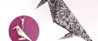
Small glider made from ceiling tiles
Materials:
- ceiling tiles - 4 mm plywood - bamboo skewer - sushi stick - rubber band for money - thread - cardboard
Tools:
- cutter - pen - ruler - scissors - ceiling adhesives and PVA - jigsaw - sandpaper - brushes and paints
Step 1. Drawing and templates.
The drawing was made directly on a sheet of cardboard so that templates could be cut out of it later. All part sizes are indicated. From the nose, 75 mm is the distance to the leading edge of the wing and the boundary along which the plywood nose piece will be measured.
Step 2. Cut out and glue the model.
If the drawing was drawn on thick cardboard, then the details on the ceiling can be cut out directly according to the templates rather than drawn. I cut out the tail internal part from the remains of the ceiling, so it is made of two parts, but it can also be made in one piece.
Step 3. Painting the model.
Before painting, it is better to first draw the contours with a pen for greater accuracy, or even paint the parts first, and only then glue them, but this is more convenient for everyone. If you don’t have acrylic paints, you can paint the model with felt-tip pens and even paste it with colored tape. In this case, we use acrylic paints - blue and orange.
Step 4. Making a starting device.
In fact, the launcher is a kind of slingshot to launch the model higher. To make it, you will need an elastic band for money and a sushi stick (or any other strip).
TTX models:
Length – 30 cm Wing span – 30 cm Weight – 16 grams
A short flight video:
Receive a selection of new homemade products by email. No spam, only useful ideas!
*By filling out the form you agree to the processing of personal data
Choosing the right model
A homemade device must certainly have some important qualities, which can be found out when studying a suitable option in the store.
What will the glider look like? For a beginner in this business, it is often difficult to achieve the correct design, which is why it is so important to adhere to the general rules.
For those with minimal design experience, it will be quite difficult to make a model, so it is recommended to choose something lightweight, but no less elegant than store-bought counterparts. There are only two main designs of this aircraft, the creation of which does not require much effort or expense. It is for these reasons that they will be the most optimal choice.
The first option is based on the principle of a designer; it is assembled and soars into the air right at the test site.
The second option is prefabricated, has an integral structure and is stable. Its creation is quite painstaking and hard work. Not every glider pilot is able to make one.